Introduction
March 29, 2024
Hagai Pettel
While most users run ASM 500 from the user interface, there are occasions when a user needs to run it from a command line. ASM 500 was not designed to run in this fashion; the GUI does a lot of data prep and organization before it launches the conversion engine; however with sufficient preparation it can be accomplished.
In this article we are going to show how to run the ASM 500 engine, dxf2gbr64.exe, with line linking turned on and de-embedding turned on.
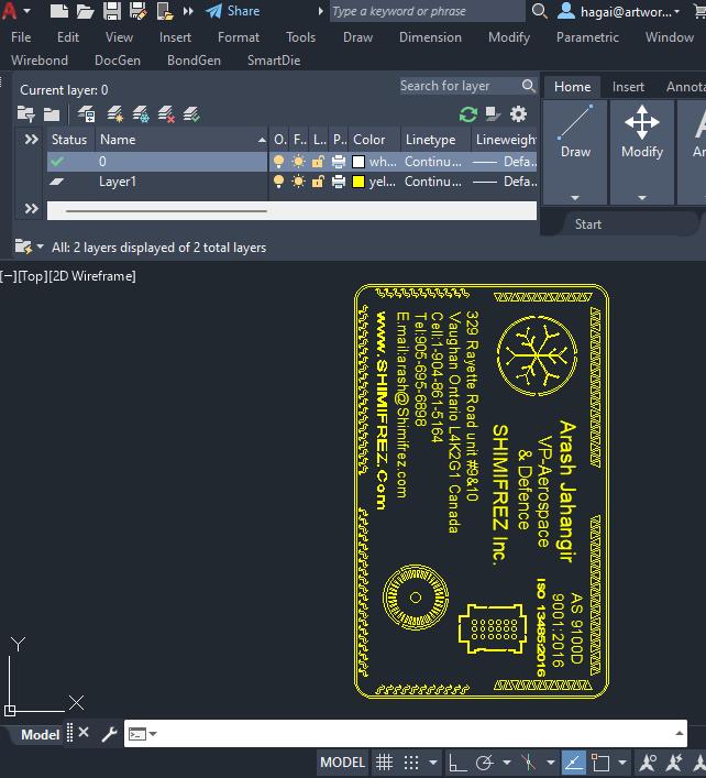
The DXF File to Convert
|
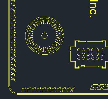
We are working with a DXF file which contains some polylines and text. The manner in which the file was drawn requires that line linking is used (since not all regions were drawn using zero width closed polylines) and also de-embedding must be used to get a proper ouptut. A zip file containing the .DXF, .bat, .rsp, .lst and .apt file can be downloaded to follow along with this tutorial. |
 |
|
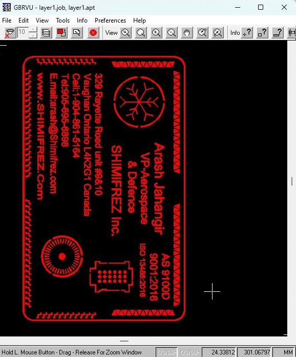
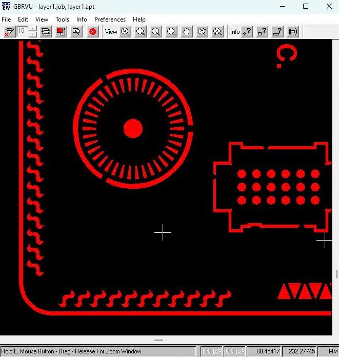
De-embedding Required You can see that there are boundaries inside of boundaries. In order to achieve the correct output, the ASM 500 engine must analyze all boundaries and determine which boundaries are embedded inside of larger boundaries. The program then has to redraw the mask boundaries so that the polarity reversal is explicit. This process we call de-embedding. |
 |
Layers to Process
In this design there is only one layer to convert. However, you can use the same procedure to convert multiple layers.Layer1 - the only layer with data
Drawing Units?
AutoCAD's DXF File format does not contain a setting that indicates the units of the geometric dimensions. In order to produce a correct mask, the units have to be known and passed to ASM 500 by the user. In this example the units are in millimeters.
Ready to Start
In addition to the command line, we'll need to create 3 separate text files.
Response File - this contains the arguments for the dxf2gbr64.exe engine.
Aperture File - this contains the apertures and Gerber settings for the conversion
List File - this contains a list of layers to process and the name of the output file to use
The Command Line
This should execute the DXF2GBR64.EXE engine and pass it the response file as the first argument followed by a 0. (The zero is a window handle and must be present). It's recommended to use full path names and to quote the arguments with path and file names.
Example
"c:\WCAD\asm500_700\dxf2gbr\dxf2gbr64.exe" "@c:\wcad\Asm500_700\500_batch_embedding\convert.rsp" 0
The Response File
This file contains a single line with the arguments that control the behavior of DXF2GBR64.EXE. Here are the contents of the response file convert.rsp
"c:\wcad\Asm500_700\500_batch_embedding\test_de-embedding.dxf" MM 0.001 "@c:\wcad\Asm500_700\500_batch_embedding\2.LST" 1.0 -z -lnk -t1 -on17,18 -c:0 "-cfg:c:\wcad\Asm500_700\500_batch_embedding\gerber_mm.apt"
Example
The arguments are all on a single line but we show them separately in order to annotate each argument.
"c:\wcad\Asm500_700\500_batch_embedding\test_de-embedding.dxf"                   full path and file name of the DXF file to convert

MM                                              Units of the input/output data (INCH or MM)

0.001                                           resolution used for line linking

"@c:\wcad\Asm500_700\500_batch_embedding\2.LST"                       use this list file to get the layer names to convert

1.0                                             scale factor

-deemb                                          turns on de-embedding behavior

-z                                              Enable De-embedding

-lnk                                            link lines and arcs to form closed boundaries. If you do not
                                                want linking use -nlnk.

-t1                                             trace mode 1 -normally with this type of conversion we
                                                are not making use of trace mode.

-on17,18                                        turn outline on and alternate between d17 and d18 apertures.
                                                for data to be de-embedded this is standard.

-c:0                                            set compensation = 0 (compensation never worked that well, so
                                                best to insure it is not working by setting to 0.

"-cfg:c:\wcad\Asm500_700\500_batch_embedding\gerber_mm.apt"                   read configuration and aperture data from gerber_mm.apt
The Aperture File
This file contains the apertures defined in the Gerber data as well as some additional parameters.
Example
APTUNITS mm                    units for this aperture file
FORMAT 4.4                     Gerber data format
SUPPRESS LEADING               suppress leading zeros
ABSOLUTE on                    Gerber about coordinates will be absolute
SUPPRESS CR                    suppress carriage return in Gerber output
GBR_END M02                    use M02 at end of Gerber file
LINK on                        Turn Line Linking On
CIRCULAR OFF                   turn circular interpolation off - mandatory for de-embedding
TEXT D10                       use D10 to draw text
LINE d10                       use D10 to draw any "free" lines
MSCALE 1.0                     ?????
ARCRES 9                       Set Arc resolution to 9 degrees
ARCSAG 0.0                     Set ArcSag to 0 (disabled)
FONT C:\wcad\asm500\txt.shx    define a primary font file (for text)
FONTDIR C:\wcad\asm500\        define a font directory
REMOVE_DIM off
REMOVE_HATCH on                ignore hatching
DEEMB 1                        turns on de-embedding type 1 (no cut lines)
FONTDIR C:\wcad\Asm500_700\dxf2gbr\fonts                        Fonts folder
D10 0.0250000 d Round 0.0250000 0.0250000
D11 0.0500000 d Round 0.0500000 0.0500000
D12 0.1000000 d Round 0.1000000 0.1000000
D13 0.2000000 d Round 0.2000000 0.2000000
D14 0.4000000 d Round 0.4000000 0.4000000
D15 0.8000000 d Round 0.8000000 0.8000000
D16 1.0000000 d Round 1.0000000 1.0000000
D17 0.0000000 d Poex 0.0000000 0.0000000
D18 0.0000000 d Poex 0.0000000 0.0000000
The List File
This file contains one or more lines. Each line specifies a DXF layer name followed by the Gerber file name we wish to produce. Both should be quoted.
In our example, here is what our list file looks like:"layer1" "c:\wcad\Asm500_700\500_batch_embedding\layer1.gbr"

