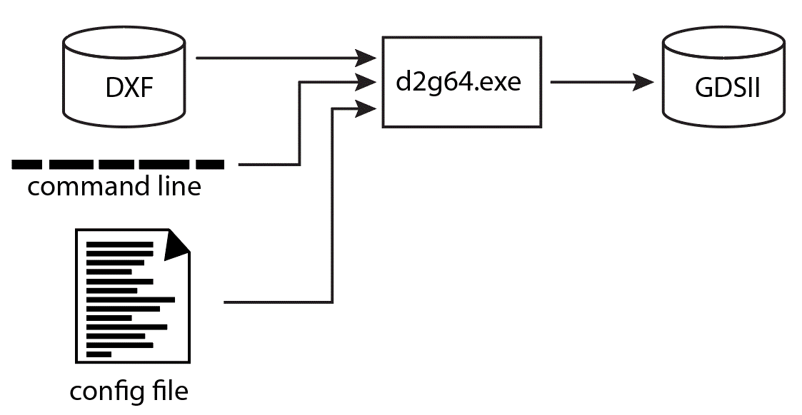
This app note describes how one would bypass the GUI and launch the engine directly; either from a script, framework or another program.
To convert DXF to GDSII execute the d2g.exe engine with the correct command line options and the required resource (config) file.

This step is not mandatory -- but in some cases the user has no idea what layers are present in the DXF file. It will be helpful to extract the names of those layers so that the config file can control the mapping of AutoCAD layer names into GDSII layer numbers. The d2g64.exe engine can be run in "scan" mode where it does not do any translation but instead scans the DXF file and returns a list of layers and blocks used in the file.
Scanning a DXF File
d2g64.exe <dxf input file> -lscan output_file
where
d2g64.exe
the path and filename of the dxf2gds translation engine
input_file
the DXF input file name. use double quotes if the path or name has spaces in it.
-lscan <output_file>
scan the DXF file. If no output_file is specified then it will create one in the current directory using the input_file_name and suffix .lyr.
Example
"d:\wcad\asm3500\d2g.exe" "d:\test\planar.dxf" -lscan
this would produce the ascii file planar.lyr in the current directory. If you wanted the output file to go somewhere else and have a different name you could use the command line:
To see the contents of a lyr file click here
The d2g engine reads an ASCII configuration file that contains layer mapping information and also translation controls. There are quite a few options, so details are available on the configuration page.
Note: the long command line is broken below for clarity. Do not place any CR/LF's in the command line.
"D:\wcad\Asm3500\d2g.exe"
D:\test\vector_test.dxf
-gds D:\junk\qckvu\vector_test_from_dxf.gds
-cfg:D:\test\sample.cfg
-nolink
-gap:0.001000
where
"D:\wcad\Asm3500\d2g.exe"
is the full path to the translation engine. Double quote this if there are spaces in the paths or file names.
D:\test\vector_test.dxf
is the input DXF file to convert.
-gds D:\test\vector_test.gds
is the name (and path) of the output GDSII file.
-cfg:"d:\test\sample.cfg"
is the name of the configuration file to use.
The following command line options are generally used:
-nolink
do not link lines and arcs. Alternative is to use -link
-gap:0.001000
if linking were on, this would be the search radius around each line or arc's endpoint. The value is in the GDSII units.
In addition to link | no link, and the -gap arguments, there are additional ones:
-emblevel
if present, de-embedding is activated and the GDSII output is organized using data types to indicate the boundary's level of embedding.
or
-deemb
boundaries are sliced and butting to form the clear areas.
or
-demb_cut
Boundaries are generated using cutlines (re-entrant)
Directory Path and File Names
Notice that because all files referenced include the full path name, the required files could be located anywhere on the system.
Warning - it has come to our attention that if very long path directories are used the command line interpreter may not be able to handle the total length and the engine may not run correctly.