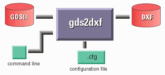
The gds2dxf command line
The translator is run from a command line. A quick summary of the command line syntax can be obtained by typing:
$ gds2dxf -h
The complete command line and arguments are shown below:
gds2dxf infile outfile topstr [[-q] [-iM,N,..] [-xM,N,..] [-cfg:file]]

where

gds2dxf      name of the translation engine

infile       name of the GDSII stream file to process.

outfile      name of the DXF file to produce.

topstr       name of the structure to start processing from. Generally
             this would be the top level structure in the GDSII file
             but not necessaryily so if you do not want to start at the
             top.

             If you do not know the name of the top level structure you
             can use the equal sign (=) and the engine will attempt to
             determine the top level automatically by choosing the
             structure with the most dependents.

-q           this option tells the engine to run in quiet mode and not to
             output status to the stdout. If you are calling gdsdxf from
             another program you generally will use this option.

-iM,N        layers to include. If -i is not listed then all layers will be
             converted. If -i is used, you must then list (comma delimited)
             all layers to convert.

-xM,N        layers to exclude. this argument is more helpful if you wish to
             convert all but a few layers i.e. -X8,9 will convert all layers
             in the GDSII file to DXF except for 8 and 9.

             you cannot use -i and -x at the same time.

-namlen:N    limits structure name lengths to N. Some versions of AutoCAD cannot
             support block names with more than 31 characters.

-cfg:file    instructs gds2dxf to read the specified file and to use the
             directives found in that file for conversion. If you do not
             specify  a .cfg file on the command line, gds2dxf will first
             look in the  current working directory for a file called GDS.CFG
             and then will look in its own bin directory for such a file. If
             no file at all is found then program hardwired defaults are used.
Command Line Example
/home/cad/asm3500/bin/gds2dxf

         /home/cad/demo1.gds

                  /home/cad/output/demo1.dxf

                            =

                                -i30,31,50

                                     -cfg:/home/cad/demo1.cfg
In this example we launched gds2dxf from its installed directory, selected the gdsii file called demo1.gds and had it translated to demo1.dxf. We requested the program to automatically use the top level structure (=) and to only convert layers 1,2,3 and to use a configuration file called demo1.cfg.
|
