AutoCAD's polyline is a very versatile geometry. However this makes for complications when converting to GDSII paths.
| AutoCAD Polyline | GDSII Path |
|---|---|
| may have constant width | SAME |
| may have "0" width/open | SAME |
| may have "0" width/closed | BOUNDARY |
| may have variable width | NOT SUPPORTED |
| may use arcs | NOT SUPPORTED |
| may be "closed" | NOT SUPPORTED |
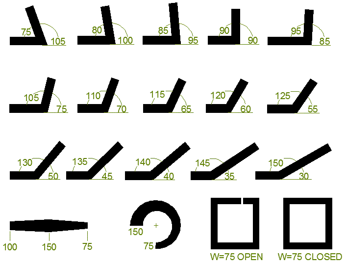
We've created a test file of polylines as shown below:

The purpose of this test file is to verify how the DXF2GDS program converts them into either paths in GDSII (if the TRACE option is selected) or into Boundaries if the OUTLINE option is set. We can also verify the behavior of the MITER function. You can download path_miter_test_case.dxf (305 KB)
Let's look at several conversion options.
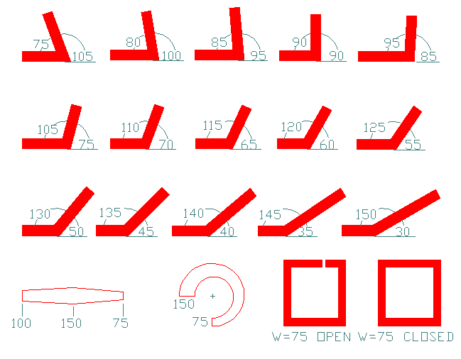
a) TRACE=ON
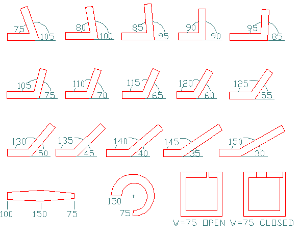
b) OUTLINE=ON, MITER=OFF
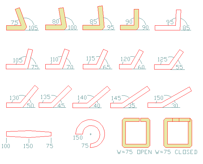
c) OUTLINE=ON, MITER=ON
TRACE=ON

One can see that two of our test polylines were output as boundaries even through TRACE=ON. That's because there is no way to represent the data correctly using GDSII Paths.
OUTLINE=ON, MITER=OFF

Here all polylines have been converted into boundaries. Notice that the sharply turned polylines were not mitered. This is usually not the best way to make the conversion into boundaries so there is also an option to miter the bends which we will see in the next illustration.
OUTLINE=ON, MITER=ON

All of the boundaries highlighted in yellow have their corners mitered. Mitering starts at 90 degrees and is applied to all turns equal to and greater than 90. This prevents the "dumb" mitering routine from forming a sharp point that extends way beyond the desired distance from the bend's center point.