Transformation
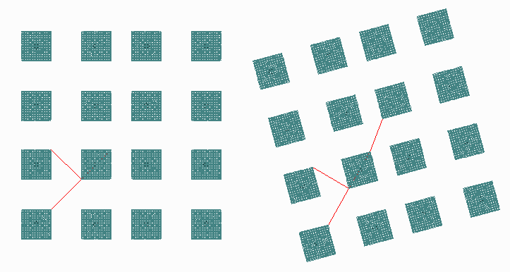
The repeating cells placed into a GDSII file for a FOWLP array are not placed as consistently as an array on stepped wafer would be. Because each device is placed independently into a new matrix, there are small offsets in the position and also the placement may be slightly rotated. This page shows how GDSII cell placements are mapped to the CSV information.

Figure 1: GDSII sample file oneuparray.gds 1.12 MB zipped
This file consists of a repeating cell named ONEUP; it has been placed (using SREF) 32 times.

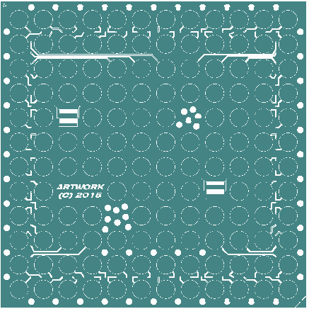
Figure 2: The repeating cell, ONEUP. It is centered at 0,0.
GDSII Placements
We can start by examining all 32 SREF placements on the GDSII side. (This is done using Artwork's GDS2ASCII converter and then extracting the SREF lines.)
STRUCT oneup_array
SREF ONEUP M0 1.0   0           0          0
SREF ONEUP M0 1.0  90   -10000000          0
SREF ONEUP M0 1.0 180   -10000000  -10000000
SREF ONEUP M0 1.0 270           0  -10000000

SREF ONEUP MX 1.0   0    18428514  -10000000
SREF ONEUP MX 1.0  90    18428514          0
SREF ONEUP MX 1.0 180     8428514          0
SREF ONEUP MX 1.0 270     8428514  -10000000

SREF ONEUP M0 1.0  90     8428514   19827779
SREF ONEUP M0 1.0 180     8428514    9827779
SREF ONEUP M0 1.0 270    18428514    9827779
SREF ONEUP M0 1.0   0    18428514   19827779

SREF ONEUP MX 1.0  90           0   19827779
SREF ONEUP MX 1.0 180   -10000000   19827779
SREF ONEUP MX 1.0 270   -10000000    9827779
SREF ONEUP MX 1.0   0           0    9827779

SREF ONEUP MX 1.0  15    41565387    8569613
SREF ONEUP MX 1.0 285    31906129    5981422
SREF ONEUP MX 1.0 195    29317939   15640681
SREF ONEUP MX 1.0 105    38977197   18228871

SREF ONEUP M0 1.0  15    56777774   22998521
SREF ONEUP M0 1.0 285    59365965   13339263
SREF ONEUP M0 1.0 195    49706706   10751073
SREF ONEUP M0 1.0 105    47118516   20410331

SREF ONEUP MX 1.0 285    54838513   -8401092
SREF ONEUP MX 1.0 195    52250323    1258167
SREF ONEUP MX 1.0 105    61909581    3846357
SREF ONEUP MX 1.0  15    64497772   -5812901

SREF ONEUP M0 1.0 285    46697194  -10582551
SREF ONEUP M0 1.0 195    37037936  -13170742
SREF ONEUP M0 1.0 105    34449746   -3511484
SREF ONEUP M0 1.0  15    44109004    -923293
The ASCII conversion for the GDSII SREF record is organized as follows:
Col 1: SREF - keyword indicating a structure reference placement.
Col 2: cell_name - the name of the cell being placed.
Col 3: Mirror Flag - M0 indicates no mirroring; MX indicates mirroring in X. (There is no GDSII mirroring in Y, so one will never see MY.)
Col 4: Scale Factor - we are not varying the scale factor.
Col 5: Rotation - this is a value in degrees and measured counter clockwise from the X,Y insertion coordinate.
Col 6: X placement. This value is in nm and must be interpreted using the user units and resolution. In our example file the database unit is um and the resolution is 1000. So a value of 8428514 = 8428.514 um.
Col 7: Y placement. Same as X placement.
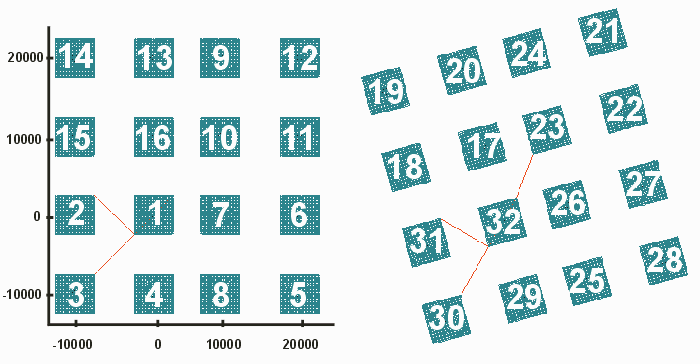
If we label the layout in the same order as the SREFs appear we will see that this is the placement order:

Figure 3: GDSII Array labeled by placement order.
CSV Output
The CSV output produced by GDS2GBR_CSV can be seen below. I have reordered the data in order to match the order of SREFs to enable easier comparison.
UNITS, MM
Frame.GBR,0
0.00000,0.00000,0.000000,N,1.000000

ONEUP.GBR,32

  0.00000,   0.00000,   0.000000, N, 1.000000
-10.00000,   0.00000,  90.000000, N, 1.000000
-10.00000, -10.00000, 180.000000, N, 1.000000
  0.00000, -10.00000, 270.000000, N, 1.000000

 18.42851, -10.00000,   0.000000, X, 1.000000
 18.42851,   0.00000,  90.000000, X, 1.000000
  8.42851,   0.00000, 180.000000, X, 1.000000
  8.42851, -10.00000, 270.000000, X, 1.000000

  8.42851,  19.82778,  90.000000, N, 1.000000
  8.42851,   9.82778, 180.000000, N, 1.000000
 18.42851,   9.82778, 270.000000, N, 1.000000
 18.42851,  19.82778,   0.000000, N, 1.000000

  0.00000,  19.82778,  90.000000, X, 1.000000
-10.00000,  19.82778, 180.000000, X, 1.000000
-10.00000,   9.82778, 270.000000, X, 1.000000
  0.00000,   9.82778,   0.000000, X, 1.000000

 41.56539,   8.56961,  15.000000, X, 1.000000
 31.90613,   5.98142, 285.000000, X, 1.000000
 29.31794,  15.64068, 195.000000, X, 1.000000
 38.97720,  18.22887, 105.000000, X, 1.000000

 56.77777,  22.99852,  15.000000, N, 1.000000
 59.36597,  13.33926, 285.000000, N, 1.000000
 49.70671,  10.75107, 195.000000, N, 1.000000
 47.11852,  20.41033, 105.000000, N, 1.000000

 54.83851,  -8.40109, 285.000000, X, 1.000000
 52.25032,   1.25817, 195.000000, X, 1.000000
 61.90958,   3.84636, 105.000000, X, 1.000000
 64.49777,  -5.81290,  15.000000, X, 1.000000

 46.69719, -10.58255, 285.000000, N, 1.000000
 37.03794, -13.17074, 195.000000, N, 1.000000
 34.44975,  -3.51148, 105.000000, N, 1.000000
 44.10900,  -0.92329,  15.000000, N, 1.000000
Col 1: X placement (mm)
Col 2: Y placement coordinate (mm)
Col 3: Rotation in degrees (CCW)
Col 4: Mirror Flag N=no mirror, X=mirror about X
Col 5: Scale Factor
Placement Illustrations
Below we have made illustrations of some of the placements and the corresponding GDSII parameters vs. the CSV parameters.

Figure 4: First 4 placements with corresponding SREF and CSV parameters.
Interaction of Rotation and Mirroring
Placement No. 17 has both mirroring in X and a 15 degree rotation. The illustration below shows how the final layout for this placement is arrived at.

Figure 5: Placement 17 includes both mirror in X anda 15 degree rotation.
