Stripe Orientation

By default, gds_rip subdivides the image into "horizontal" stripes whose width covers the entire image (unless the user has defined a specific data window) and whose "height" is determined by the RAM allocated to the bitmap buffer.

The resulting output is typically a series of wide bitmaps.

The bitmap data from each band could be compressed and written to disk. Later the individual bands could be concatenated if a single large bitmap file was desired.


RIP stripe orientation is horizontal by default.


Vertical Striping w. User Defined Width

For some imaging or scanning applications this may not be a suitable way of subdividing the output. It may be preferable for the stripes to run vertically. Further, the application may require a specific bitmap width to match the scanning head.


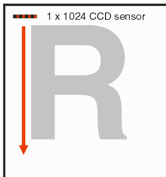
Consider the case where a linear LED array (1x1024 pixels) is scanned vertically across a mask for imaging purposes.

The bitmap needed to control the LED should be 1024 pixels wide and as high as the entire image.

One cannot obtain such a bitmap by rotating or mirroring the input CAD data. It is necessary for gds_rip to internally slice the data vertically and to rasterize vertically.

In order to support such applications, we have added the -vertical directive to gds_rip that can be used force banding in a vertical orientation.

Further the user can fix the width of the band to match that of his equipment using the clip_bitmap_dim directive.

  CCD moved vertically across the mask.


To achieve the desired bitmap the user should set two directives:

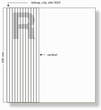
-vertical
-bitmap_clip_dim:1024

The first directive tells gdsrip to orient the bands vertically instead of the default horizontal. The second directive tells gdsrip to set the band's width to exactly 1024 pixels instead of calculating a band width based on the -ram setting.

In order to support such applications, we have added the -vertical directive to gds_rip that can be used force banding in a vertical orientation.

Further the user can fix the width of the band to match that of his equipment using the clip_bitmap_window directive.

  vertical banding with 1024 pixel width


Setting the RAM

Even when defining the exact width of the band it is still required to set the RAM to be used for the bitmap. The calling program should calculate the amount of RAM required based on the width of the vertical band and the height of the data. For example, if our image area is 300 x 300 mm and we are rasterizing at 1 um per pixel then the RAM required for a 1024 pixel wide band is:


  RAM = [1024 x 300 mm x 1000 pixels/mm]/8 pixels per byte

  RAM = 38.4 MBytes

  (293 bands generated to completely rasterize the image area)

If the calling program sets -ram: to a value less than 38.4 MB then an error will be returned. It is OK to set the -ram value much larger than the required amount.


If No Width is Set

If no band width is set then the width and number of bands is determined by how much memory is available to compose the bitmapped image. (We call the memory used to hold the bitmap the "raster buffer.") If -ram:1000 (1000 MB) is specified then the bitmap for each band must fit into 1GB. For the above mentioned values:

 1E9 bytes  = [width(pixels) x 300 mm x 1000]/8 (pixels/byte)

 band width(pixels) = 26665

 12 bands (11 full and one partial band)


Next Multithreaded rasterization