|
Metal over Contact over Diffusion
The basic building block in digital IC’s is a pair of stacked FETs whose output are hooked together. This
is realized as follows:
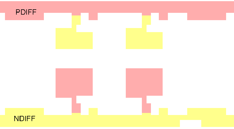
Figure 2: Two diffusions are performed - NDIFF for N channel FETS and PDIFF for P channel FETS.
Now openings called contacts are made in the insulating layer.
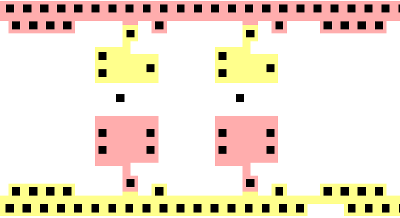
Figure 3: Contact openings
Poly is now deposited. The poly forms the FET's gate structure.
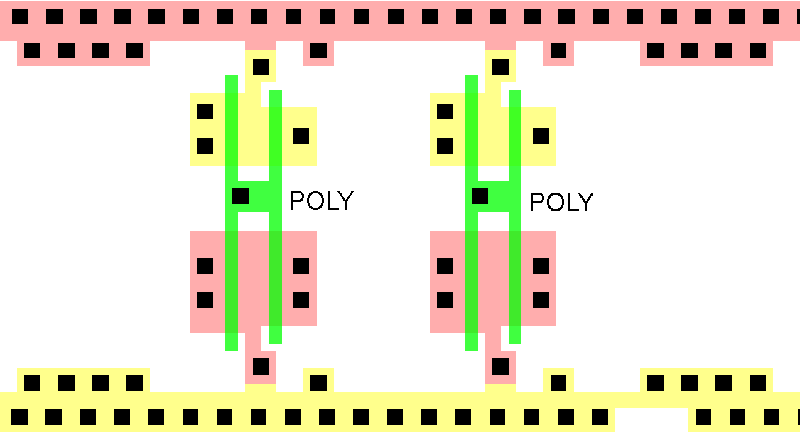
Figure 4: Poly is laid down to form the gate structure.
M1 is deposited providing the electrical connections to the gate, source and drain.
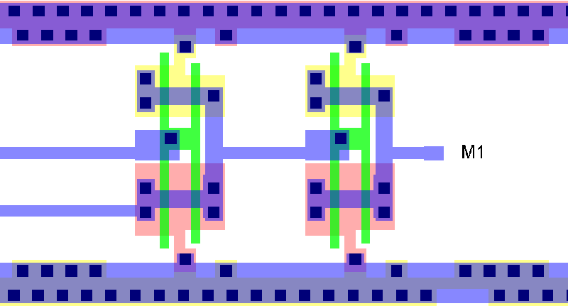
Figure 5: M1 is deposited.
Identifying the "Drivers"
If we then do a Boolean operation - M1 UNION CONTACT UNION DIFF we will end up with small "boxes" which have been labeled "D" in the illustration below. These are our drivers.
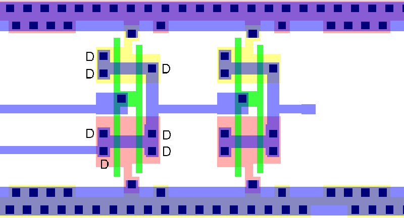
Figure 6: drivers are identified by union of M1, CONTACT and DIFFUSION.
Aggregating Drivers into a Single Box
One problem that becomes apparent from this example is that for a single driver there may be multiple contact points. If we return all of the coordinates that we find using the M1 over Contact over DIFF Boolean, the resulting display may be more confusing than helpful.
The solution is to define a parameter (GAPx and GAPy) which defines a "box" around each point. We then merge the overlapping boxes, find the center of the merge and return that point. By properly selecting the value of the GAP (which is generally process dependent) the user will obtain a much clearer idea of where the driver is located.
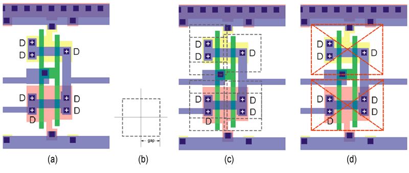
Figure 7: a) too many driver coordinates; b) define gap for merging; c) boxes before merging; d) after merging only two points reported.
Adding Driver Detection to the Technology File
Assuming the driver detection engine has been "turned on" via a proper license, the only requirement to use it is to add a new block to the technology file.
A sample block is shown below:
DRIVER_INFO              keyword that starts the block
METAL 16:0               define the M1 layer (GDSII layer:datatype)
CONTACT 15:0             define the CONTACT layer
DIFF 11:0 12:0           define the diffusion layer(s)
ENDDRIVER_INFO           keyword to end the block
If needed, one can use derived or synthesized layers.
|
