Insertion Control
Overlay creates a merged GDSII file by creating a new top level structure in the output file and then referencing (SREF) each of the input files from this new top level structure.
By default, Overlay does not apply any transformations to the reference: X,Y = 0, no mirroring, no rotation, scale = 1.
But a user many need to "shift" one or more of the merged files to align it correctly with other files. This can be done using the XY Offset field in the Overlay program.
Example
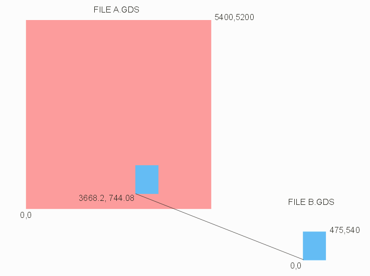
We have a chip layout (File A.GDS) which contains a memory cell. We have a second file, File B.GDS, which is a variant of the memory cell. We want to overlay (i.e. merge) B.GDS so that it aligns with the original memory cell. That way we can easily view the differences between the original design and the variant. We are able to determine that the SREF placing the original memory cell has an insertion coordinate of 3668.2,744.08 um. We are interested in inspecting layers 3:0,17:0 and 30:0.

Here's what our input to Overlay would look like:
| Input | Structure | Input Layer | Output Layer | XY Shift |
| A.GDS | TOP | 3:0,17:0,30:0 | ||
| B.GDS | TOP | 3:0,17:0,30:0 | 103:0,117:0,130:0 | 3668.2,744.08 |
The user will be able to open the merged file, zoom into the area where the original memory cell is placed, and toggle on/off the layers so that any variations can be clearly visualized.
