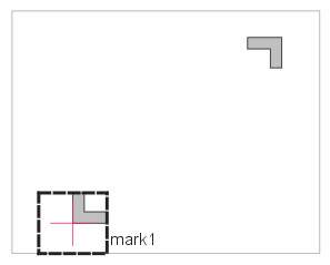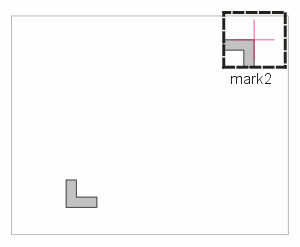


As part of the Care Area file export, the user is expected to define two
registration sites on the chip. These are used to align the CAD data with the
inspection machine coordinates. The export includes an ASCII file, config.csv,
that summarizes the registration info, two TIF bitmap files that are images of
the region surrounding the registration marks and rectangles in the care area
file that define the location of the registration sites.


The user normally will turn off cell outlining and turn on at least one layer
that contains the registration marks. This might be the passivation opening
layer and a top metal layer. The user will then zoom into the region of the
first mark. Finally, the user will “click” on a vertex of a polygon that is used as the registration mark. See below:


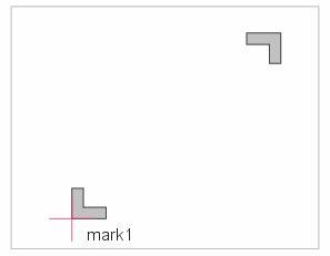


snap mode is automatically set to vertex.

The CA Wizard will then create a “box” centered about the selection point that exactly contains the extents of the
polygon. This is the box that is exported with the care area rectangles in the
CA file.


At export time, the CA Wizard creates a “snapshot” in TIF format of data displayed inside of this “box.” This process is repeated for the second registration mark.


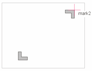


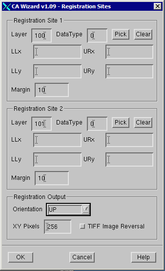

For each registration site the user must assign a unique combination of layer
and datatype for the output file. These layer and datatypes should not be
duplicated later by selection set assignments of layer and datatype.
To define the site, click on the Pick button and moving to the display, click on an entity’s vertex. (Note: you must turn at least one layer on - you cannot pick on a
structure outline)
The user must also set an orientation: UP, DOWN, LEFT or RIGHT. Normally the
user should not change the size of the TIFF image as the inspection software
expects a 256 x 256 image.
The margin value (in um) is added to the box created after selecting the
alignment entity. This allows the bitmap to capture a bit of the region beyond
the actual aligment entity.
The user may choose to reverse the polarity of the TIFF image by checking the TIFF Image Reversal checkbox.


