PROLITH Mask Extractor
The PROLITH Mask Extractor Plug In is used to select a small window of polygons from a GDSII or OASIS file and save the selection in Prolith's MSK file format.
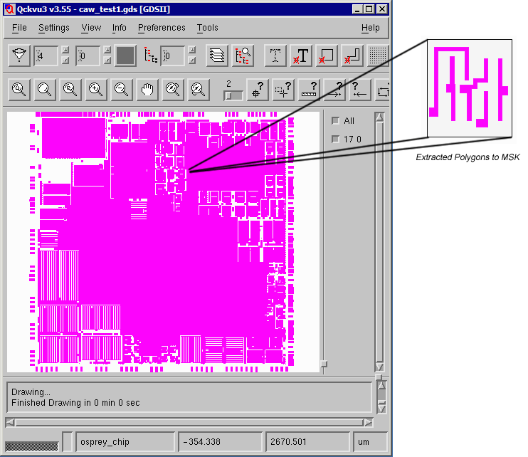

PROLITH Mask ExtractorThe PROLITH Mask Extractor Plug In is used to select a small window of polygons from a GDSII or OASIS file and save the selection in Prolith's MSK file format.  |
||

|
click here for a short video demo. | |
|
Make sure that only the layer you wish to extract is turned "on" Zoom in to the region you wish to extract. This need not be exact but in deep enough to see where you want to draw the extraction window. Open the dialog by clicking on the Tools drop down menu and selecting Create PROLITH Mask File ... 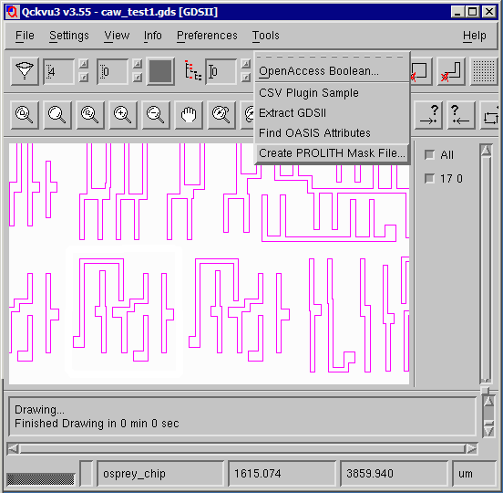 A dialog box will open showing the layers that are to be extracted. If you need to change the layer (digitized data) transmission and phase values do so. You can also change the background (field) transmission and phase values. 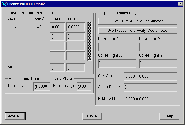 Select the window to extract. You can do this in three ways: (a) Click on Get Current View Coordinates and the corners of the display will be used as the extraction window. (b) Click on Use Mouse to Specify Coordinates and click on two opposite corners of the desired window. (c) Enter the window manually - using the lower left and upper right coordinates. In the screen shot below the mouse was used to define the mask region.
Any geometries crossing the selection window will be clipped to the edge of the extraction window. Once the mouse has been used to select the window, the Prolith dialog is updated. Note that units displayed in the Prolith dialog are in nanometers. 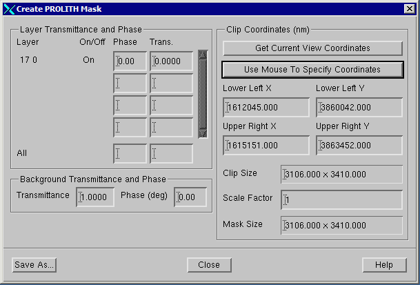 Save As - Once you have determined that all settings are correct and that the desired polygons are inside your window, click on Save As. You will be able to set the name of the mask file that is produced. If you need multiple selections, just define a new window and hit the Save As button again. Be sure to use a different file name for each selection. |
The MSK OutputThe KLA PROLITH Mask File is an ascii file with a short header followed by polygon data. A sample is shown below. The data units are always in nanometers. The coordinate data is automatically shifted so that the lower left of the window is located at 0,0. This is to prevent overrun for data that is located far from the origin.
[Version]
7.2                             <-- file version
[Parameters]
sample2                         <-- name of mask
3618.000,1444.000,0.000,0.000   <-- mask dimensions (top,right,bottom,left)
3618.000,1444.000,0.000,0.000   <-- simulation dimensions (top,right,bottom,left)
0.0010                          <-- background transmittance
0.00                            <-- background phase
0.000                           <-- CSE Step Size
0                               <-- Generate New CSE
0
[Data]
Polygon(0.9950, 0.00, 17)       <-- transmission, phase, GroupID
{
   711.000,1739.000
   991.000,1739.000
   991.000,1329.000
   1011.000,1329.000
   1011.000,259.000
   1141.000,259.000
   1141.000,1329.000
   1161.000,1329.000
   1161.000,1614.000
   1211.000,1614.000
   1211.000,2139.000
   1191.000,2139.000
   1191.000,3289.000
   1061.000,3289.000
   1061.000,2139.000
   711.000,2139.000
}
Polygon(0.9950, 0.00, 17)
{
   46.000,1499.000
   311.000,1499.000
   311.000,1329.000
   611.000,1329.000
   611.000,259.000
   741.000,259.000
   741.000,1329.000
   761.000,1329.000
   761.000,1499.000
   481.000,1499.000
   481.000,2139.000
   461.000,2139.000
   461.000,3289.000
   331.000,3289.000
   331.000,2139.000
   311.000,2139.000
   311.000,1899.000
   46.000,1899.000
}
Polygon(0.9950, 0.00, 17)
{
   0.000,379.000
   11.000,379.000
   11.000,509.000
   0.000,509.000
}
[CSE]
|
| Download | Price | Revision History | Install Notes |