Target Bitmap Acquisition
updated February 8, 2018
Semiconductor inspection machines often use pattern recognition to find the targets on a layout for alignment purposes. It can be useful to obtain a "synthetic image" of the target to train the pattern recognition engine. This plug-in for The Qckvu3 layout viewer makes it fast and simple to obtain target bitmaps from the CAD layout.
The camera used to recognize the target has a fixed field of view (determined by the sensor size and lens magnification) and a fixed resolution based on the number of pixels in the sensor. Common arrays of pixels used in such sensors are 1024 x 1024, 1280 x 720 and 1920 x 1280.
The plug-in enables the user to quickly define the image either by entering the pixel array size and the pixel size or the field of view and the pixel size. This enables the capture of a bitmap that exactly fits onto the sensor.
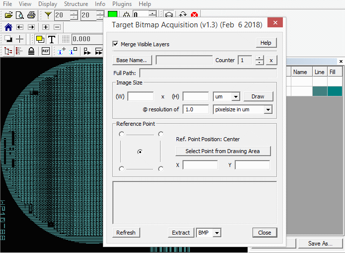
Output is written either to the TIFF or BMP format as a monochrome bitmap. For each bitmap, an ascii file is also produced that includes the center coordinate and width/height of the bitmap in user units (i.e. microns).
Qckvu3 can handle extremely large files and the incorporation of our latest rasterizer means that extracting these bitmaps from even very large files is fast.
How it Works
Open a GDSII or OASIS layout and turn on only the layer (or layers) you want to use for your bitmap. As the output is monochrome it does not matter what color your layers are assigned. Any display filters in effect are ignored when producing the bitmap.
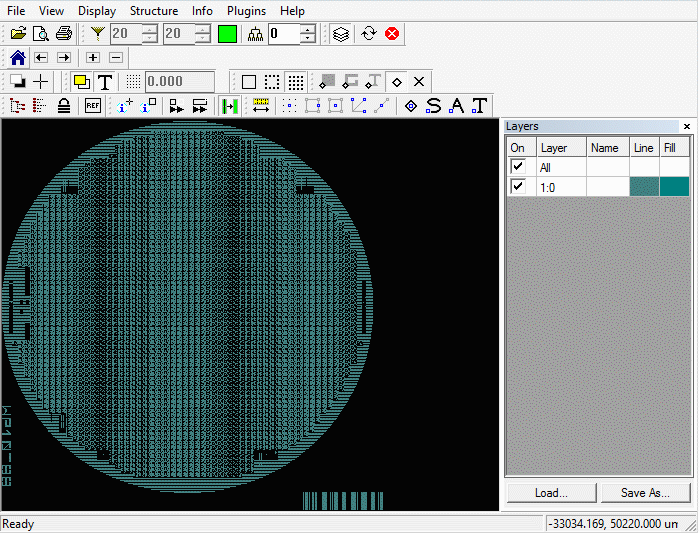
From the Plugins pull down select: Target Bitmap Acquisition.
The dialog box should open.

Base Name and Path for Bitmaps
Start by setting the output directory where the bitmaps/text files will be written and select the base name for the output bitmaps; do this by clicking on the button Base Name ... The name of each bitmap/ascii file pair will be incremented by 1 each time a new clip is taken.
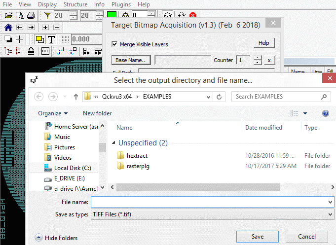
A dialog will open that enables the user to define the base name for the clips as well as the destination directory. The user can also set the output type here (BMP, TIFF or RAW).
Defining the Field of View
There are different approaches to defining the "window" and number of pixels generated.
If you know your camera's pixel array size, say 1024 x 1024, you can enter those values in pixels. Then enter the physical size of a pixel - e.g. 0.25 um. Your window will cover 1024 x 0.25 um = 256 x 256 um.
|
|
As a user you can define the width and height of the window in um and then the pixel size (in um) or the resolution in DPI. Or you can draw your windows directly on the screen and the resulting bitmap will be defined either by your pixel size or your DPI. |
Type of Bitmap Output
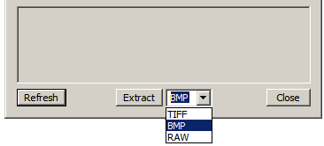
Set the bitmap output type to BMP or TIFF or RAW (no header)
The Bitmap and Text Output
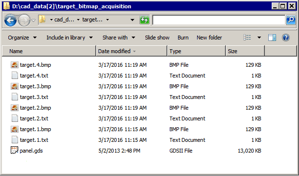
Each selection/Extract operation produces two files: a bitmap and an associated text file. If you look into the directory you selected for the output you will see something like this (after 4 target extractions.)
The ASCII Files
A sample ASCII file associated with a bitmap is shown below:
target4.txt
Image File: D:\cad_data[2]\target_bitmap_acquisition\target.4.bmp
CAD File: D:\cad_data[2]\target_bitmap_acquisition\panel.gds
Cell: TOP
Layers: 0:0
Window: Center: 419988, 514983, Width: 5120, Height: 5120 um
Resolution: 5080 dpi (5 pixelsize in um)
This text file is useful when the location information of the target is needed (say for coarse positioning of the camera) to start the alignment process.
