GDSII Net Tracing with QIS Client and QIS.This page describes the basic procedure for using our QIS Client on the PC along with the QIS Net Tracer running on Solaris to
highlight nets in the GDSII file. |
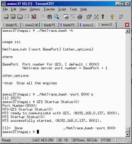
STEP 1Assuming the QIS Net Trace software is already installed (contact us for key codes), you should go ahead and start the application on your Solaris station. Go to the QIS Net Trace installation directory and run the NetTrace.bash to start the QIS service as shown below.You need to specify the port number you want to use. You also need to know the IP address of the UNIX system. These two things will be entered later to the QIS Client on the PC side. |
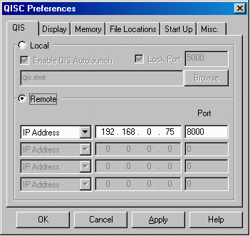
STEP 2On the PC side, we can now start the QIS Client application. After the GUI comes up, go to File > Preferences to open the QIS Configuration menu.In this menu you need to specify the IP address and the port where the net tracer started from. You also want to check On the Remote which allows you to Browse for the file to view on the UNIX box. |
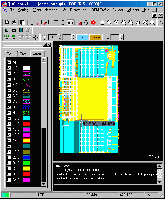
STEP 3From the File pull down menu, click on Open and navigate through the UNIX directory until you find your file. Select it and hit OK.For this example, we will go with the demo_ntrc.gds we supply with the QIS Net Tracer. The program will go through the Scanning and then Loading phases. Once done, you will see the chip on the screen. |
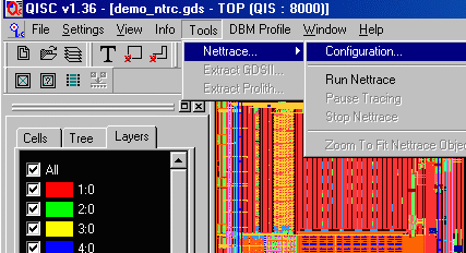
STEP 4At this point we can start the Net Trace and go to the Configuration menu |
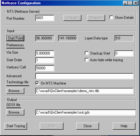
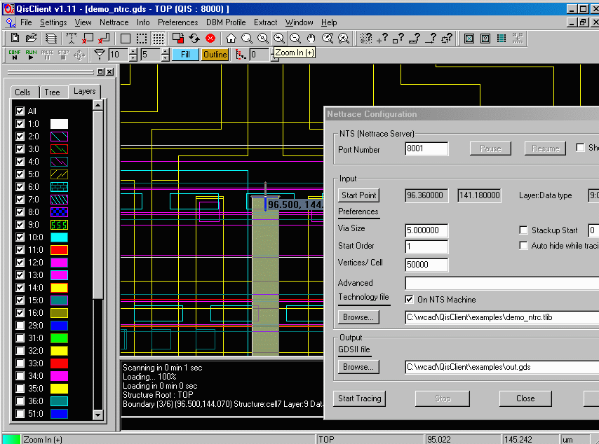
STEP 5There are a few things we need to setup in this menu.First, we want to pick a start point. Use the QIS Client to zoom to around 96.5,143.6 and then click on the Start Point in the configuration menu. At this point, move the mouse to this XY coordinate and click with the mouse inside the polygon in that location. The polygon will get highlighted and the x,y coordinate will appear in the configuration menu. Another important thing is to pick the Technology file. This file defines the layer stackup. We supply you with a file called demo_ntrc.tlib located in the QIS Net Trace examples directory which will work for our example file. Last, define an output GDSII file. This will be a GDSII file of the net which will get created by the software. |
STEP 6Start the Net Tracing by clicking on Start Tracing, and the program will start highlighting the polygons associated with the point and stackup file you picked. |
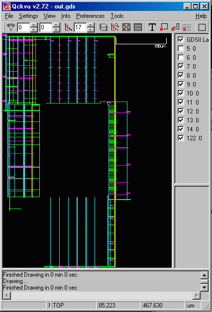
STEP 7It will also create a GDSII file with the net that was derived from the layout. |