Viewing OASIS Files and Converting them to GDSIIThis page describes the basic procedure for viewing OASIS files and converting them to GDSII. |
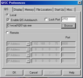
STEP 1The first step is to start QISC on your Windows station. From the File > Preferences menu, select the location where the QIS server is running.In our example, we will use the local QIS and use the Autolaunch option. Alternatively, a user may choose a remote QIS server which can run on another Windows, Linux, or Solaris workstation. In this case, use the remote option and specify the IP address and port number where QIS is running. ![]() |
STEP 2From the main menu, select the File > Open option and select the demo5.oas file. The QISC will load the file and display it on the screen.![]() |
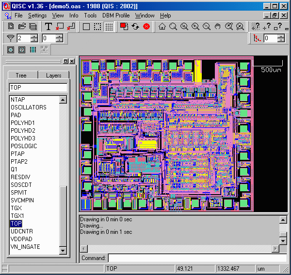
STEP 3Click on the Cell menu and double click on the cell called "TOP" - In this file, this is the top cell.The full chip image should be visible now. At this point you can use any of the clients commands like zoom, measure, pan, object info, layer and cell control, and many other commands available from the pull down menus. ![]() |
STEP 4You may also type in QIS commands in the Command box at the bottom of the QISC screen.In our case, we will use the command get_gdsii c:\temp\demo5.gds to save a GDSII file from this OASIS file. Please note that the GDSII file generated is a flat file. Here is how the GDSII file looks like in Qckvu.. ![]() |
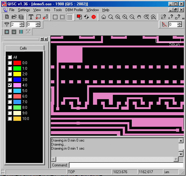
Controled conversion from OASIS to GDSIIA user may want to only convert certain layer or window from OASIS to GDSII. The QISC allows you to do so as well.In this example, let's extract data from layer 4 only and from this window 1000,1000 to 1200,1200. You can specify this window by going to the View > Zoom to XY Coordinate menu. The image should look like the one below... ![]() |
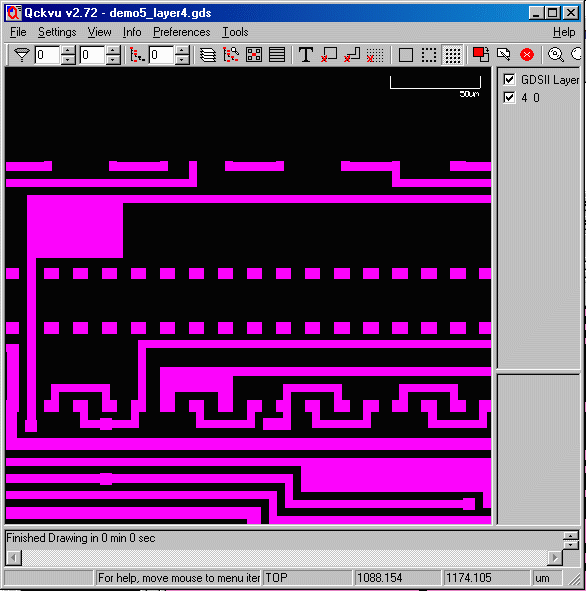
Save to GDSIITo save this image to a new GDSII file, you type in the following QIS command get_gdsii c:\temp\demo5_layer4.gdsHere is how the new GDSII file will look like... ![]() |