

After a successful installation and loading of the RandGen menu into AutoCAD the user should see a new drop down item: RandGen.

Click on the Randgen menu item and then click on: Generate Random. This will pop up the user interface seen below:
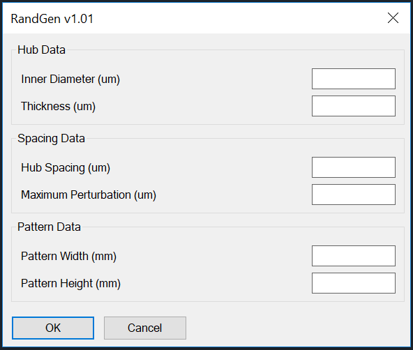
The fields may be empty or they may "remember" the values used in a previous run.
Inner Diameter (um)
The inner diameter of the hub.
Thickness (um)
The thickness, "W" of the hub. I.D. + 2W = O.D.
Hub Spacing (um)
The center to center spacing of each hub with respect to its 6 neighbors.
Maximum Perturbation (um)
The maximum value of that the hub's center may be moved from the nominal location. This max value is limited to prevent hubs from touching or overlapping.
While the units for the hub dimensions are in um, the pattern size is in mm for convenience.
Pattern Width (mm)
The desired width of the randomized pattern. Note that the resulting pattern's width will vary a bit since the number of hubs must be an integer.Pattern Height (mm)
The desired height of the randomized pattern. Note that the resulting pattern's width will vary a bit since the number of hubs must be an integer.
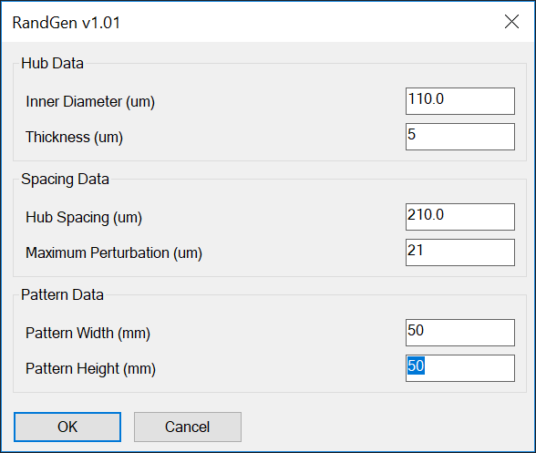
Below you can see some parameters we entered to generate a mesh. Our mesh is 50 x 50 mm in size.
When we hit OK and wait 30 seconds we then see on the screen:
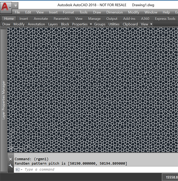
All that is left to do is to SaveAs a DXF file.
In the command window the program reports the precise values to use if you wish to array this pattern to cover a larger area without seams.

First, the program insures that the hubs on the outer rows and columns are placed so then when arrayed (allowing a single hub overlap) no visible seam is present. Second, the precise pitch in X and Y is reported by the program.
We don't recommend doing the step and repeat in AutoCAD. It is preferable to convert first to GDSII or Gerber and then use a CAM tool to do the array.
In the sample below I first generated a 5 x 5 mm pattern and then copied it once to the right and once above.
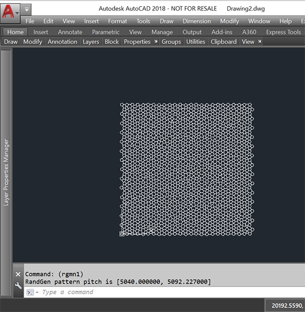
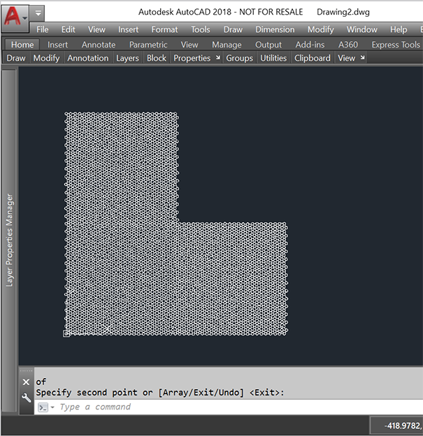
Any seam you see in the above images is solely due to AutoCAD display artifacts. As soon as you zoom in deeper, the artifacts disappear.