
When SFGEN processes an ODB++ file, the circuit traces (aka lines or paths) are converted into GDSII boundaries due to the fact that the ODB++ data is run through Boolean operations during the conversion. So the output from a PCB (sample.tgz layer=top) consists solely of boundaries.

But what if your application prefers GDSII paths to make the interconnections between pads? The new path recovery engine addresses that issue.
Path Recovery works because during the SFGEN processing, a file called GDX (we call this the auxiliary file) actually retains all of the trace information from the ODB++ file. However one cannot just take these traces and dump them into the output GDSII file for a couple of reasons:
a) If the ODB++ traces appear on a negative layer they can't be represented in the GDSII output because they end up as "cutouts"
b) The trace data has to replace the metal already in the output file by using a Boolean operation and the resutling cut-outs in the pads have to be "healed"

There are two ways to run SFGen's Path Recovery - from the SFGEN GUI (see details below) and from the command line. For details on the command line syntax go to this page: Path Recovery Command Line.
To activate path recovery, press the Advanced button on the main menu which will take you to the tabbed Advanced Settings dialog; select the tab: Path Recovery.
Then check the box next to Path Recovery.

The Path Recovery function includes a large number of controls and parameters that can be adjusted to "tune" the path recognition routine as well as to control the output.
Output Layers, Boundaries, Paths
Path Recovery produces a GDSII output which includes: paths (from traces/lines) pads (boundaries that have been recognized as pads) and boundaries (everything else). By default all three of these outputs are placed on layer 0:0 (where 0:0 indicates layer:datatype)

However the user can specify the layer for each of the three groups by filling in the appropriate layer numbers.
For example, if 10,20,30 is entered into the field for this control then:
Boundaries : 10
Paths : 20
Pads : 30

Depending on the user's requirements, Path Recovery's output can be filtered. This section of the dialog window controls what gets output.

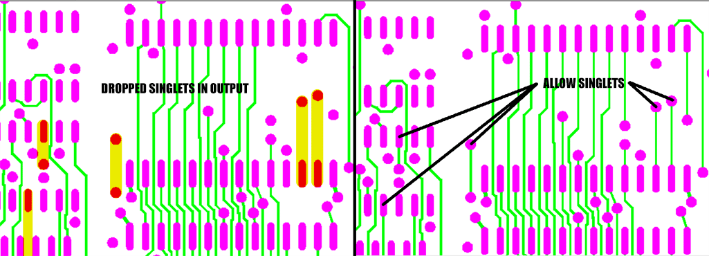
Allow Singlets
If "Allow Singlets" is checked, then a straight path connecting two pads will be passed to the output.
Include Pads
If "Include Pads" is checked, then any boundaries that are recognized as pads are output to the specified pad layer. This includes round, oblong, square and rectangular shapes. Custom pad shapes such as thermals are not recognized.
Participating Only
If "Participating Only" is checked, then only pads that terminate a path are output to the pads layer. Standalone pads are not output to the pad layer.

Termination Requirement
Choose one of the three path termination options:
None
If checked, then all paths are converted - even those that don't have a pad termination on either end of the path.
Singly OK
If checked, then paths that have either a single termination (or both sides terminated) are converted.
Double Terminated
If checked, only paths that have both ends terminated are converted.
Output Source Path Data (positive only) on Layer L[:D]
This is a debugging feature and is used if one needs to examine the boundaries that were the source for the path conversion. Most users have no need to check this. If you do check this make sure to specify a layer (or layer:datatype) that does not match any of the main outputs for boundaries, paths or pads.
The parameter fields can be used to "tune" the recovery of paths. However tuning the recovery using these parameters requires a deep understanding of both the program operation and the nature of your data.
In most cases, the only parameter to adjust would be the "Nom. Width" by entering a value that is approximately the width of most of the paths one expects to recover.
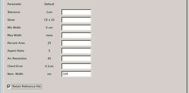
A value (in um) which sets the precision associated with general computations, vertex matching (default: 1um)
The sliver value (in um) associated with Boolean operations; (default = 10 X chord error)The purpose of the sliver operation is to remove small "slivers" of conductor that arise from noise in the Boolean operations.
Min WidthA value (in um) that sets the minimum width of a PATH to be output. Default = 0
A value (in um) that sets the maximum width of a PATH to be output. Default = No limit.
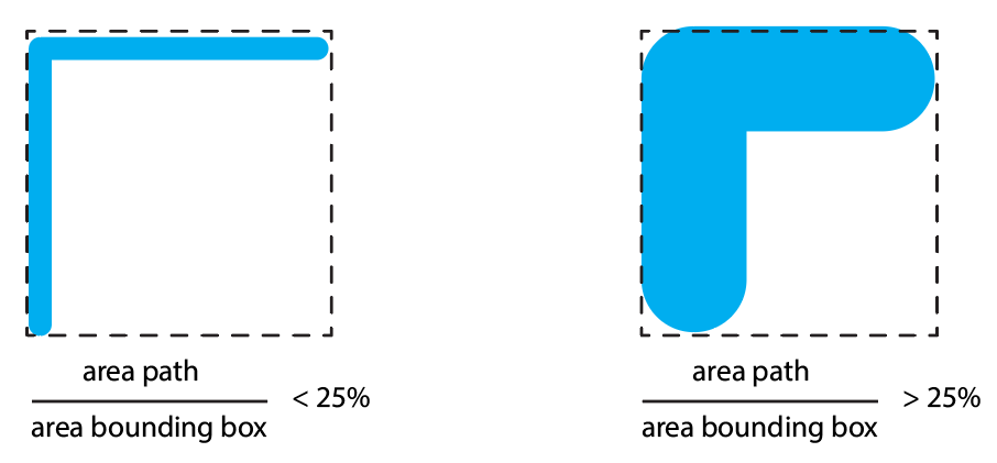
The ratio of the area covered by a path (two segments or more) to the area of the bounding box surrounding the path. If the computed ratio is greater than that value set by the user then the path is NOT output. (Default = 25%)
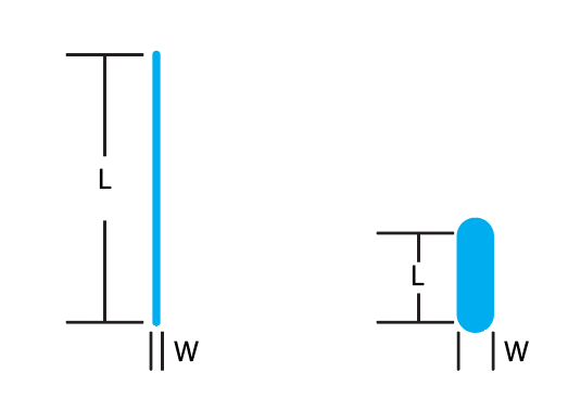
The Length/Width ratio of the candidate PATH. If the PATH's L/W is less than the value entered, the PATH will not be output. For example, if the Aspect Ratio = 5 and the path is 100 um wide and 300 um in length it will not pass the ASPECT ratio test and will not be output. Default=5
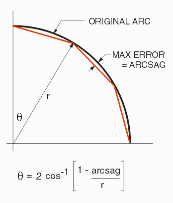
The arc resolution (in degrees) to be used when converting candidate PATH data to polygon data for Boolean operations. Because this works together with the chord error parameter, it is normally set to 45 degrees ( a very coarse value) which allows the setting and use of chord error to determine the number of vertices. Chord error is a more dynamic approach to setting the number of vertices per arc as it takes into account the arc's radius. Default = 45 deg.
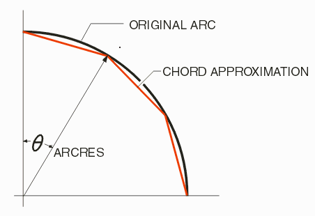
The value of chord error (previously referred to as arg sag), in um, to be used when converting candidate PATH data to polygons data for Boolean operations. The software then determines how many segments (vertices) are needed to approximate the arc to achieve this amount of error. This minimizes the total number of vertices and still insures that the error is not any larger than what the user specifies. Default = 0.1um.
Enter a nominal width for your PATHS. For example, if you PCB has many traces with width of 150 um then enter that value here. This will change the other parameters to values that work "best" on paths of this width.
If checked, the reference file used to generate the path recovery output is saved to the SFGen working directory.