Copper Fill for Gerber Files
The manufacturing of a printed circuit requires that the density of the metal across the board or panel be made as uniform as possible. If there are large areas devoid of metal two problems can crop up: a) etching of the board may not be as uniform as desired and b) after lamination the board may have a tendency to warp or even delaminate.
To minimize these problems the board shop generally imports the design data, panelizes it and then applies a copper fill (also known as thieving) across the surface of the panel.
Some of our customers who work with very unusual design layouts may prefer to prepare the panel themselves. In this case they need to do both etch compensation (another topic) and thieving.
The CopperFill program generates the array of copper rectangles normally used to fill in the empty areas on the board or panel.
The User Interface

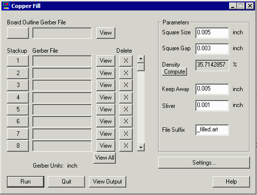
Board Outline Gerber File
This should be a file that contains just a single connected draw that forms a closed area. It will define the outer edge of the board for the filling program.
Stackup Gerber FilesEach row accepts single RS274X file (may have internal layers) that defines each of the conductor layers to be etched. If your inner layers are substantially filled with copper then you would not need to process these layers. However if they are sparse (used for signal routing) then they should be added to the list.
Parameters
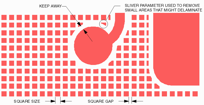
Square Size - the size of the square conductor used to fill the empty areas of the board.
Square Gap - the with of the gap (both X and Y) between squares.
Density - the percent copper density achieved based on the square size and gap. Press Compute to see it updated after any change to square size or gap.
Keep Away - the distance to keep away from the conductor already in place.
Sliver - removal of tiny pieces of the fill copper based on their sliver size.
File Suffix - the name of the file the program creates. It begins with the base of the input file and applies this suffix to the output file name.
All parameter units must be entered in the same units as the input Gerber files. All input Gerber files must share the same units, format and zero suppression.

Settings
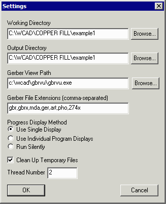
The settings dialog contains additional controls for the copper fill program.

Working Directory - the directory where all intermediate files are written.
Output Directory - the directory where the completed (i.e. copper filled) Gerber files are written.
Gerber Viewer Path - the path/name of the Gerber viewer i.e. C:\WCAD\GBRVU\gbrvu.exe
Gerber File Extensions - default extensions for Gerber files.
Progress Display Method - type of progress display - Use Single Display routes messages from all engines to a single progress display; Use Individual Program Displays allows each "engine" to open a window for its own messages; Run Silently suppresses all displays.
Clean up Temporary Files - if checked, after run is completed delete all of the temporary files created during the processing.
Thread Number - number of concurrent threads to use for the copper fill modules that are multi-threaded. The bigger the input data the more advantage there is to using multiple threads.
