
|
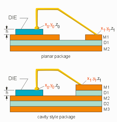
3D Wire DescriptionNETEX-G gets only 2D wire coordinates from its input data (Gerber) but in real life the wires follow a 3D path from die pad to package pin. Therefore to accurately model them the user must add some extra information - Z values for the start and end points and a wire model with its parameters. Z Heights First, we assume that all wires originate on a die surface with a common Z-value. We will know the Z value by defining the height of the die body along with the conductor or dielectric layer that the die body sits on. We will know the height of the other end of the wire by defining on which metal layer it falls on. NETEX-G looks "down" through the stackup from the wire end and figures out on which conductor layer it will land. Therefore it can support both planar packages and cavity or stepped packages. 
|
|
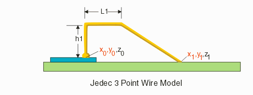
Z-Profile The wire's z-profile is defined using a model with parameters. While Artwork has developed some very sophisticated user-defined models, we are not going to use those at present - instead we are going to use two very old models developed by JEDEC - the JEDEC 3 point wire model and the JEDEC 4 point wire model. Jedec 3 Point Wire Model The JEDEC 3 point wire model requires just two parameters - h1, the height that the wire rises from the die pad and L1 the distance it travels horizontally before beginning a straight line descent to the package finger pad. 
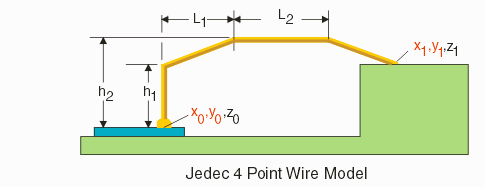
The three point model works well for relatively short wires. The illustration is not to scale as h1 and L1 are exaggerated for clarity. Jedec 4 Point Wire Model Longer wires generally have a bit of arc in them much like the arch of a bridge -- this helps to reduce the wire sag that might result in a short circuit. The JEDEC 4 point model has additional parameters that enable the user to approximate an arc as shown in the illustration below: 
Wire Syntax in the ASCII file Wirebonds are not normally converted to boundaries unless the user sets them as METAL layers instead of WIREBOND layers in the stackup definition. Instead, NETEX-G outputs a special WIRE entity that includes the layer, diameter and starting/ending coordinates of the wire. Layer Table Wire layers are defined in the layer table. They have no "thickness." They are generally listed at the top of the layer list. All wires sharing a common layer will share the same wire model and model parameters so it is not unusual to see two, three or even four wire layers. B_LAYERS 1 W1 WIREBOND 0.00 GOLD 0xE6843CFF 0.00 0.00 0.00 2 W2 WIREBOND 0.00 GOLD 0xE6843CFF 0.00 0.00 0.00 3 M1 METAL 0.10 COPPER 0x444044FF 0.00 0.00 0.00 END_LAYERS
Column Definitions Wire Models The wire models are defined within their own WIREMODELS block as shown below: B_WIREMODELS WIRE1 W1 0.025 JEDEC4 0.09 1 0.168 0.75 WIRE2 W2 0.025 JEDEC4 0.19 1.026 0.288 0.748 E_WIREMODELS
Column Definitions The units for the wire models can be read from the LIBRARY statement which follows. (We did this because we desired to maintain backward compatibility with tools that don't support the new wire info and which would be unhappy if this new data appeared inside of the LIBRARY section) Die Parameters The die outline and thickness is entered into NETEX-G directly by the user. This information can then be used to "draw" a 3D solid of the die and to calculate the Z value of the wire's origination. DIE DUMMY_DIE 3 0.1 -1.64 1.64 1.64 -1.64
Column Definitions The die height is clearly required but if the corner information is missing, the 3D application can simply not draw the die body. The units for the die can be read from the LIBRARY statement which follows. (We did this because we desired to maintain backward compatibility with tools that don't support the new wire and die info and which would be unhappy if this new data appeared inside of the LIBRARY section) Wire Entries Wire entries will always be found inside of a NET section since they are conductors. Each wire entry requires multiple lines as shown below: WIRE 2 250 W2 -14600 -10790 -43180 -37060 3 ENDEL
Line 1 Line 2 Line 3 Line 4 Line 5 Notes use the layer name on line 1 to find the wire's layer model and associated parameters. use the stackup position on line 4 to find the wire's Z value on the package side use LIBRARY units and resolution to determine the meaning of the X,Y coordinates: i.e. LIBRARY LEADFRAME_3D_MRG_NEALL.NW unit:MM grid:10000 then -43180 = -43180/10000 = -4.318 MM |