

Importing IPC D 356 into NETEX-G


First the user must set up the layer stackup in NETEX-G. Once this is complete
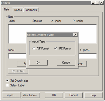
click on the Labels ... button from the main dialog and then click on the Import ... button.
You will be given a choice of importing either AIF or IPC Format. Select the
radio button IPC Format and click OK.


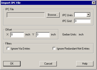
The Import IPC Dialog
Browse - use this button to select the IPC file to load.
IPC Units - it should not be necessary to enter the units - however some poorly
constructed IPC files do not contain unit information in which case the user
must select the correct units which are always inches or mm.
IPC Grid - it should not be necessary to enter the grid - however some poorly constructed
IPC files do not contain correct grid information in which case the user must
enter the correct value.
Offset - Occasionally the IPC coordinates and the Gerber file coordinates have been
offset. This is a terrible practice but some PCB designers still do it. In such
a case, one has to “guess” the offset, import the data and then view it to determine whether the test
points line up with the test locations. If not, change the offset until the
test point data lines up with the pins.


