Introduction
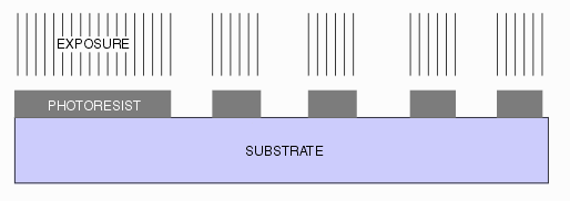
For most semiconductor mask applications one wants photo resist to be very contrasty - either you get a completely dark region or a completely clear region depending on whether the resist has been exposed to light or not exposed.
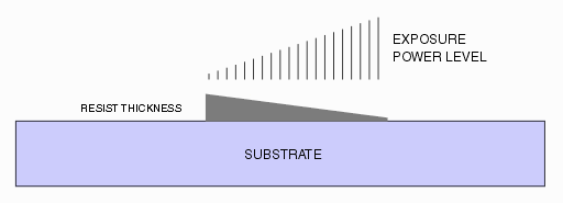
If one selects a more linear resist and is able to adjust the power level from point to point it is possible to create 3D structures in the resist. These can then be used to make multiple copies of 3D objects.
Software Flow
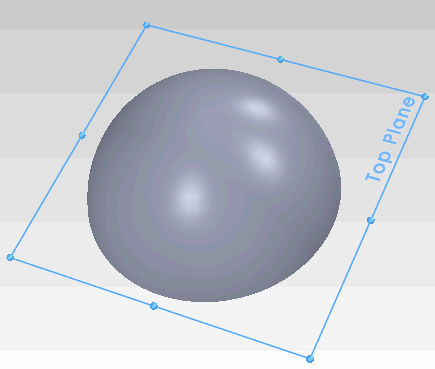
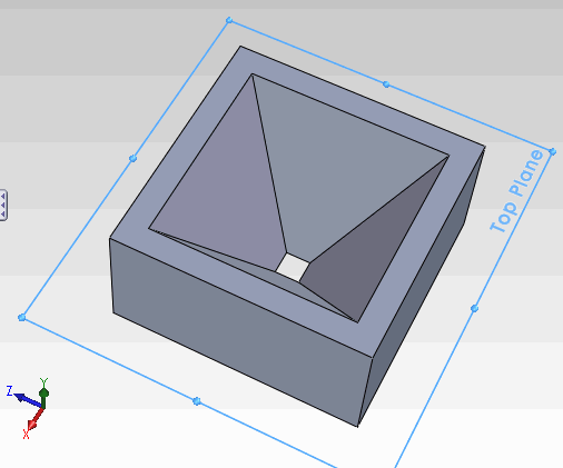
3D objects are generally created using a 3D MCAD (Mechanical CAD) program such as SolidWorks, ProE or Inventor. All of these programs can produce a standard output file known as STL. STL consists of thousands of triangles that cover the faces of the 3D object.
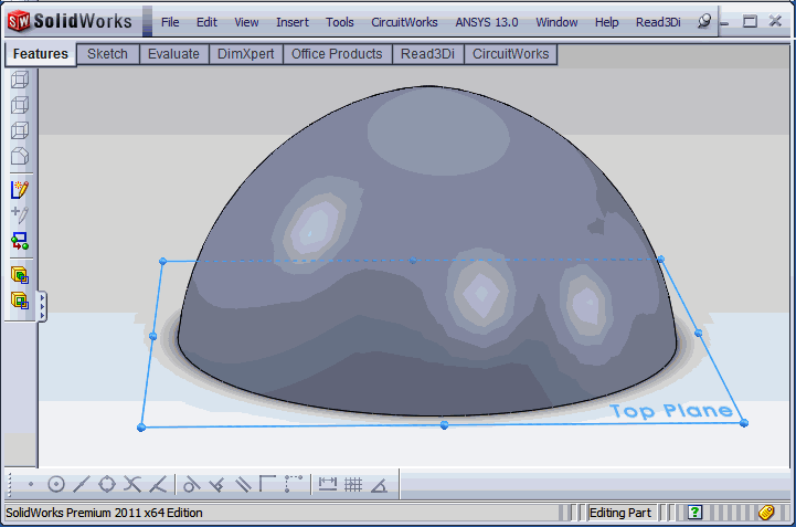
STL2MIC reads the STL data and "slices" it at multiple levels. Each level essentially represents a power level for the laser that will generate a desired height in the photoresist. The number of slices corresponds to the number of power levels that the laser can support. The maximum is currently set to 256 slices.
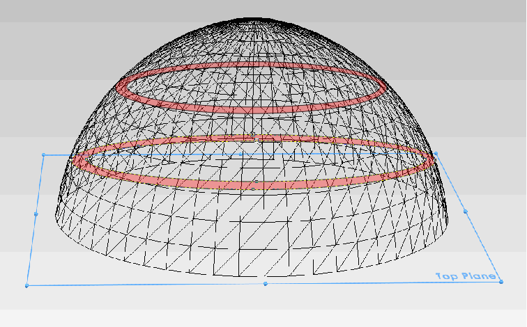
The output of STL2MIC consists of polygons on a series of layers. Each layer represents a small range of Z heights for the 3D object. In the image below we cut the hemisphere into 32 slices - you are looking at the outline(black) and slice 11 (cyan) and slice 19 (aquamarine)
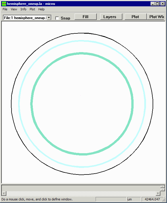
The laser writer front end software reads this multi-layered MIC file and then converts the layers into pixel-based power levels that will modulate the laser as it scans the photoresist.

