
 |
ODB Route Notes for 3DA route layer in ODB can be used to cut out sections in the PCB. It may include both the board outline and can include slots or cutouts inside of the board outline. Since the route layer is used to drive a CNC cutter, it will generally consist of finite width traces. |
||
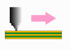 The router is a high speed rotating bit that moves across the board leaving a slot opening ... |
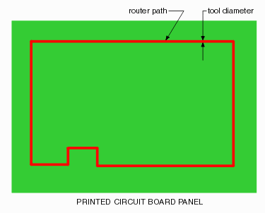 |
|
|
Case 1 - Single Route In this case there is a single continuous route that is used to remove the board from the panel. When converting this into a cutting boundary, our software uses the inner edge to account for the tool width. 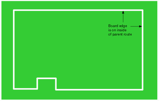 Case 2 - Inner Cutouts Many boards have inner sections cut out to accomodate components or heatsinks. In this case the cutting edge is the "outer" side of the route. 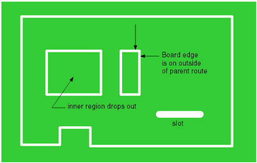 Final Results After the outer (parent) route and inner (children) routes have been taken into account, the final substrate shape looks like this:  Drill Holes Any non-plated through drills (or other drills which are determined to be for mounting purposes) will also punch through all layers of the PCB ... They are either a) included as part of their own drill file or b) included with PTH holes in which case one must mark them by tool number. Getting these mounting holes into the substrate is very important to the 3D MCAD user who is checking whether the board (and its mounting holes) fit into the mechanical housing designed for it.  Note: when modeling the substrate layers in 3D we normally don't want to generate holes for the vias but we do want to generate holes for mechanical mounting. (If we generate holes for a thousand vias the 3D file is going to be too big) |