    [PADS]
    BF=RECT 90 254
    BP750=CIRCLE 750
    DP100=SQ 100


    [NETLIST]

   ;NET    DIE PAD & COORDS     BALL PAD & COORDS          FINGER PAD & COORDS
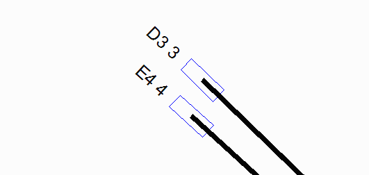
    NET3 3 DP100 -5270 4750     D3 BP750 -13335 12065      3 BF -8262.55 7648.42 45.92
    NET4 4 DP100 -5270 4655     E4 BP750 -12065 10795      4 BF -8324.01 7444.40 47.59
Suppose we wanted the wire to be offset by 50 um towards the front of the finger instead of landing in the center of the finger. [See below] How would we modify the AIF file to support this description?

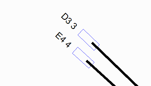
Well without "breaking" the AIF behavior we could implement this with two entries: a) Create a line to place the bond finger leaving off the die data so that we don't generate a wire. Create a new line with the die pad and a "dummy" bond finger to generate the wire where we want it.
    [PADS]
    BF=RECT 90 254
    BP750=CIRCLE 750
    DP100=SQ 100
    DUM=CIRCLE 25


    [NETLIST]

   ;NET    DIE PAD & COORDS     BALL PAD & COORDS          FINGER PAD & COORDS
    NET3 - -     -     -        D3 BP750 -13335 12065      3 BF  -8262.55 7648.42 45.92
    NET3 3 DP100 -5270 4750     D3 BP750 -13335 12065      3 DUM -8226.5  7613.7  0


    NET4 - -     -     -        E4 BP750 -12065 10795      4 BF  -8324.01 7444.40 47.59
    NET4 4 DP100 -5270 4655     E4 BP750 -12065 10795      4 DUM -8286.80 7410.80 0
This feature has been added to the most recent AIF Exporter for Cadence 16.3 which can be obtained from Cadence by downloading the ISR.
