3Di Web Page Header

Extrusions

An extrusion consists of one or more 2D closed figures in the xy plane, extruded between two z-values. Any 2D figure after the first one represents a non-touching, non-intersecting hole in the parent figure. The definition is as follows:

    EXTR <n_children> <z1> <z2>

Example

    EXTR 1 100.0 200.0

An extrusion is defined using the EXTR keyword, followed by the number of 2D figures making up the extrusion and the two z-values between which the figures should be extruded. Three types of figures can be extruded: the 2D polygon, the circle and the path.
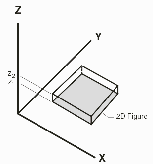
 

3Di extrusion


2D Polygon

A 2D polygon is a closed geometry lying in the xy plane, made up of unique points which form non-intersecting straight edges. The definition uses the keyword 2DPG followed by the number of points in the polygon. The points themselves follow, on multiple lines, if required:

    2DPG <n_points>
    <x1> <y1> ... <xn> <yn>

Example

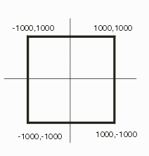
    2DPG 4
     1000.0   1000.0
    -1000.0   1000.0
    -1000.0  -1000.0
     1000.0  -1000.0

    or 

   2DPG 4 
   1000 1000 -1000 1000 -1000 -1000 1000 -1000
 

2D Polygon


2D Polygon Arc

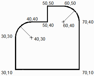
A 2D polygon arc is a closed geometry lying in the xy plane, made up of unique vertices which form non-intersecting straight edges. The connections between vertices can be either lines or arcs. The definition uses the keyword 2DPA followed by the number of vertices in the boundary. The vertex coordinates themselves follow, on multiple lines, if required:

  2DPA

    2DPA <n_segments>
    <x1> <y1> <cx1> <cy1> <r1> ... <xn> <yn> <cxn> <cyn> <rn>

positive radius ->  CCW
negative radius ->  CW

Example

2DPA 8
30 10 0 0 0
70 10 0 0 0
70 40 60 40 10
60 50 0 0 0
50 50 0 0 0
50 40 0 0 0
40 40 40 30 10
30 30 0 0 0


2D Circle

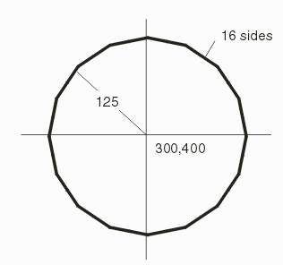
A 2D circle is a circle which lies in the xy plane, with an optional parameter defining the number of chords that may be used when rendering it.

   2DCR <x> <y> <radius> [<sides>]

Example

   2DCR 300.0 400.0 125.0 16
  2D Circle


Path

A PATH is a line with a width defined at each vertex and an endcap definition. Each vertex is defined as an XY pair and line segments connect the vertices. The endcap is optional but is normally assumed to be a half-round in order to be compatible with PCB layout tools.

PATH <n_points> [<endcap>]
<x1> <y1> <w1> ... <xn> <yn> <wn>

Example

   PATH 6 1
        
  path illustration