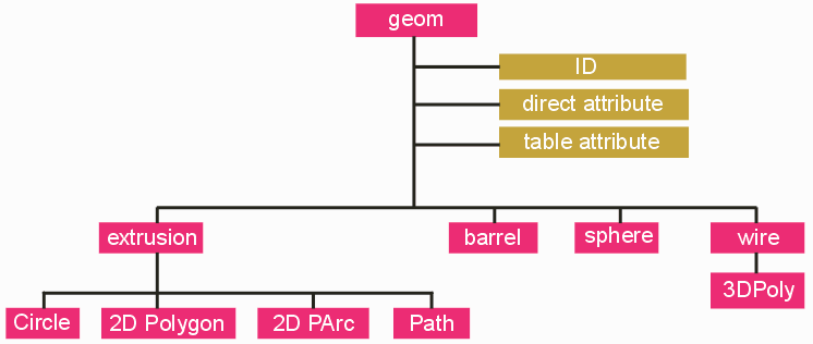
Geometries form the core of the 3Di file. This section starts with the keyword GEOMETRIES. Each geometry starts with the keyword GEOM.

Click on any block to go the specific topic.
Four classes of 3D geometries are supported which have been developed for PCB and IC package layouts
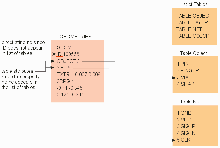
Associating properties or attributes with each geometry is what gives the 3Di database intelligence. There are two types of attributes: direct and table.
Example of a GEOM and Attribute/Properties
GEOM
ID 100001
OBJECT 4
LAYER 1
COLOR 1
NET 1
NET_PINS 1
Direct attributes are generally used only once or a few times. They take the form: ATTRIBUTE_NAME VALUE. An example of a direct attribute would be the ID (or handle) These ID's are used to correlate 3D geometries with the 2D geometries that generated them. (Cadence Allegro) Since they are, by definition, unique, there would be no reason to build a table of IDs and then refer to them by the table index.
On the other hand, a net label is likely to be used to multiple conductor geometries. In such a case a TABLE NET would be created and geometries would be labeled using the index to the appropriate net.
This is why it is required to create a list of tables at the beginning of the 3Di file. Only in that fashion can the 3Di parser determine whether an attribute is direct (i.e. the property name does not appear in the list of tables) or table based. The tables themselves can be placed at the end of the 3Di database.

While it is technically legal to write geometries with no attributes, we recommend that the 3Di writer includes these attributes at a minimum:
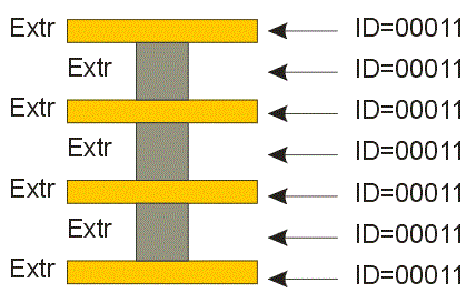
Some of our customers have requested that Artwork support the concept of padstacks in the 3Di architecture. However this concept does not work with 3Di since it doesn't "place" objects in 3Di; a pad stack is essentially a collection of nested pads and via elements. However we have recently added a PADSTACK attribute so that a 3Di parser could identify all objects associated with a particular padstack and then process them as a group.

Further, when writing a 3Di output from a layout tool that does support padstacks, we recommend that all elements of the padstack be assigned the same ID attribute. In that manner, a postprocessor can use the ID attribute to "understand" that these elements constitute a pad stack.