 |
Wire DRC | |||
|
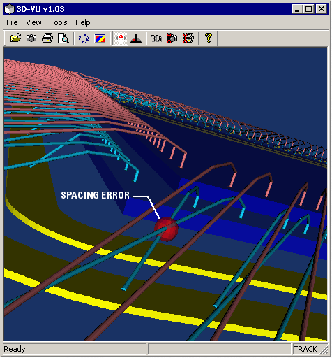
Wire DRC in 3D is used to check wire to wire spacing, wire to die body spacing and wire to pad/conductor spacing. 3DVU allows the user to define multiple spacing rules. Rules can be setup to apply to specific wire groups (tiers or loops)and can be further filtered by net and layer if so needed. The user defines a different colored marker for each type of error. Whenever the DRC detects an error it places that marker at the location where the error is deemed to be located. |

DRC Error marker indicating a spacing violation |
||
Defining Rules | |||
|
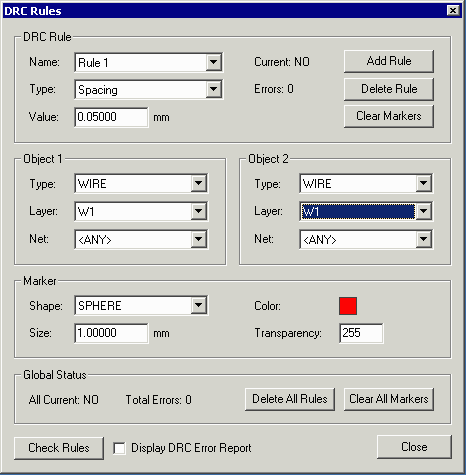
The user can define as many rules as needed for DRC from this dialog. Rule Number - Each rule is assigned its own number. Rule Type - There are several rule types. Select one from the pull down. Rule Value - The boundary value. For example if you are doing a wire-wire spacing you might pick 0.05 mm (remember that wire spacing is measured center to center) Object Type - this will be either a wire or a substrate or a conductor such as a bondfinger or pin or ring. Object Layer - if you want the DRC to limit test to objects on a particular layer then select the layer. If for all layers, select ANY. Object Net - if you want the DRC to limit test to a particular net then select the net. If for all nets, select ANY. |

3DVU's dialog for setting up DRC Rules. | ||
DRC MarkersEach error should have a unique marker description associated with it. Marker Type - select a type such as sphere or cubes are most common. Marker Size - select a marker size. We suggest that markers used for wire violations be typically 4 to 5 times the diameter of the wire for good visibility. Color - select RGB values for color (0-255). Transparency - The parameter for "A" which represents the alpha channel is the markers transparency. If A=0 the marker is solid. If A=255 the marker is completely transparent (this is not ideal since it will be invisible). A typical transparency value is 128. |
| IC Packaging Page | Download | Price | Revision History |