How It Works
Once started, the line linker attempts to create as many unambiguous "chains" as possible. However there are several cases where a chain cannot be extended. The most common are:
- more than one possible path for a chain to follow - this occurs often when there are lines under lines at at the endpoint of a chain more than one line (or arc) is found.
- the gap to the nearest endpoint is larger than the search radius. This occurs when there is either a gap or a crossing of lines/arcs where they ought, in principle, to exactly meet up.
Connecting the Chains
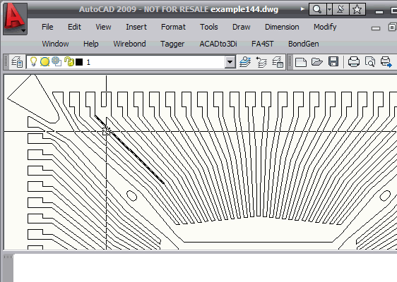
Connecting the chains is done with the user's help. A chain is presented as the "current" chain and one of the endpoints is selected. If another chain endpoint is found touching or nearby the current point the user is prompted to connect the two chains. If there are multiple chains that might be followed the user should select the "correct" one which can normally be determined by inspection. If there is nothing near the current endpoint the user can either have the chain "closed" or select an endpoint on another chain and a segement will be generated to connect them.
This is much easier to describe in a short video than with static pictures and words.

Click to Watch Video (4 minutes 20 seconds)
|


