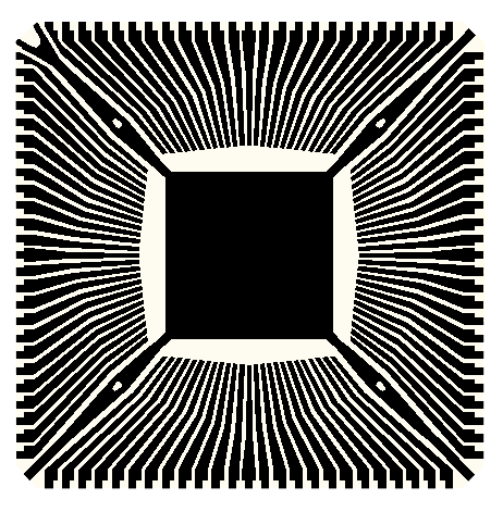
Polygon Reversal and ClippingThe leadframe designers almost always draw the reverse of the conductor - essentially they draw the regions that must be etched away leaving the metal. Therefore a boolean reversal must be done in order to obtain polygons for the conductors. |
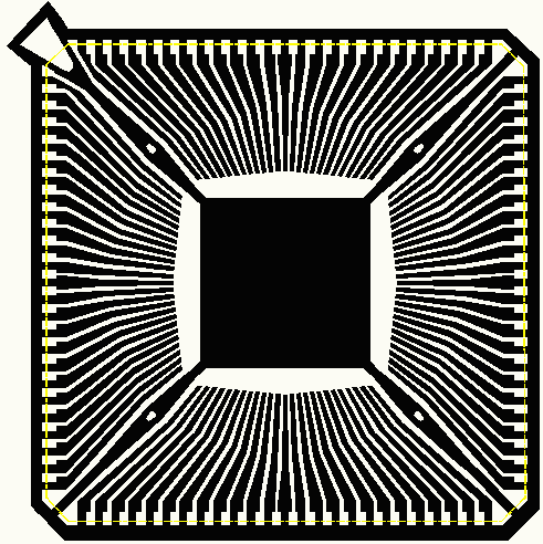
metal is black. The designer digitized the white regions. |
Clipping - leadframes are normally part of a large metal strip and because of this all of the conductors are electrically connected at the periphery. Any reversal also requires a clipping just inside ther periphery to separate the conductors - otherwise everything is short circuited. See below. |
clipping boundary set to the package outline. |
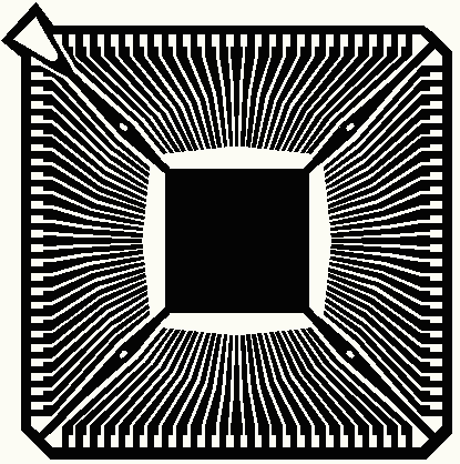
After clipping the needed polygons are now ready for to convert into "shapes" and then can be imported correctly into Cadence APD. It is not always obvious exactly where the clipping boundary should be. Generally it is just outside of the package outline. The clipping boundary need not be square but it must be drawn as a zero width closed polyline. It is also possible to define multiple clipping boundaries. |
Lead frame after reversal and clipping |
How It WorksAfter selecting Poly Reversal from the menu pulldown the user is prompted to select the desired polygons to reverse. You can use any of AutoCAD's selection options: windows, crossing, fence etc ... After selecting the polygons to reverse you must select a clipping polygon (or polygons) You will then be prompted to enter a layer name for the results. If the layer does not exist, it will be created. If the layer does exist, it will first be "emptied" so don't specify a layer name that has anything on it you wish to keep. Once you've selected a destination layer, the boolean runs. To see a short video demo click below: Click to Watch Video (2 minutes 20 seconds) |
|