How Wires are Modeled
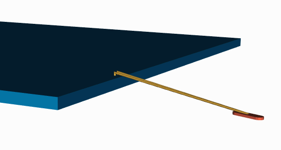
Wires are defined in 3Di by their end points and a number of vertices between the end points. A wire is also assigned a "diameter" and a number of sides. The sample below shows the various records used to define a wire.
GEOM           <-- starts with a geometry keyword.
ID 297061040   <-- a unique ID or handle (for syncing with the source in SIP)
OBJECT 1       <-- OBJECT Table index; in this case 1=WIRE
LAYER 2        <-- LAYER Table index; in this case PROFILE1
COLOR 1        <-- COLOR Table index; in this case: 255 0 0 255 (RGBA)
WIRE_MODEL 1   <-- WIRE MODEL Table index; see below.
NET 230                             <-- NET Table index; 230=VDDE_GPIO_3V3_B
CONNECT ID:298406640 ID:296935624   <-- handles of GEOM connecting to this wire
WIRE 8.900000 12                    <-- WIRE keyword, diameter and number of sides.
3DPL 3                              <-- 3D polyline with 3 vertex pairs to follow

-1141.497 2264.998 354.000          <-- x,y,z
-1141.497 2264.998 379.000          <-- x,y,z
-1565.400 3689.120 254.000          <-- x,y,z
While the wire model is referred to and available in the database, it is not actually used since the computed vertex locations are already known.
WIRE_MODEL 1
PROFILE1 8.900000 3 FORWARD
STEP
HOR 0.000
VER X 0.250
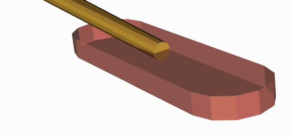
So let's examine a wire and investigate some modeling issues. In the figure below you can see the die body and two wires coming from the die and landing on a bond pad.

There are several issues here from a FEA modeling point of view.
Vertex bends - you can see that the first bend is greater than 90 degrees. This results in a sharp point where we mitered the two cylinders into a single body. Small sharp discontinuities where surfaces meet may cause mesher problems.

Wire - Finger Interference - On the bond finger side, the wire lands at an angle. We currently do not account for this and allow part of the wire's solid body to "interfere" with the solid body representing the bond finger. Again, many meshers will have problems with this representation.

Wire - Wire Interference - in this example the designer has double bonded wires to the same bond finger. Since the landing point chosen is the same, the two wire bodies interfere. FEA meshers and simulators won't digest this well.

Depending on your FEA analysis (for example electromagnetic or perhaps wire deflection with epoxy injection) the simulation engineer will have very specific needs regarding the 3D wire model. We encourage our users to contact us and explain in detail how they want their wires modeled. For the moment, we are not attempting any advanced smoothing or 3D boolean operations on the wires.
|


