
September 17, 2020
If you are trying to convert layout data such as a multi-layer PCB into Abaqus for 3D simulation you will probably first convert your board data into the 3Di format and then use 3Di2STEP (likely from within 3DVU) to produce a STEP file. Abaqus can then import the STEP data which will provide you a 3D model of your circuit board.
However the way Abaqus imports STEP data is quite annoying. It does not really follow the organization of data that is found in the STEP data. Here is what the user's choices are:
Option 1: Create a part for each solid body in the STEP file.
OR
Option 2: Import all solid bodies from all parts into a single part.
Neither option is really what most users want.
If Option 1 is selected we will end up with hundreds or thousands of parts. We don't really want that - we want a part to contain all the solid bodies associated with a single conductor, dielectric or drill layer.
If Option 2 is selected, we end up with all of our solid bodies poured into a single part. This is not helpful since we need a way to keep solid bodies made of copper (conductors) separate from solid bodies made from dielectric material.
Work Around
The work around is to create multiple STEP files from a single 3Di file - one STEP file for each layer. The use Option 2 - Import all Solid Bodies into a Single Part. You will get a part containing all the bodies for the layer you used. Repeat this until you have processed all of the board layers - both the copper conductor layers and the dielectric layers.
Handling Negative Dielectric
By "negative dielectric" we made a group of dielectric solid bodies that lie on the same elevation as each copper layer. Normally when you build an actual PCB, the temperature and pressure associated with laminating the PCB forces the pre-preg to flow between the gaps between copper traces so there is no "air" left inside the PCB.
However because we model the PCB as a series of separate layers, our model has "air" between traces on the same conductor layer.
This will cause the 3D mesher to treat these non-existant air pockets as if they were present and not only makes the mesh much more complex but will return incorrect results because of the large difference between the dielectric constant of the PCB material and that of air.
Imagine the case where you have a two layer PCB - top conductor = M1, dielectric = BOARD1, drill = D1 and bottom conductor = M2. If you need the "negative dielectric" also then you would have M1-1 to fill in the areas on M1 between traces with dielectric, and M2-1 to fill in the areas between the conductors on M2.

So how do you import this into Abaqus?
1. Use Boolean/Negative Dielectric
Use the Boolean menu item in 3DVU and define the board extents using the dielectric layer D1_BOARD. This is needed to generate a negative dielectric.
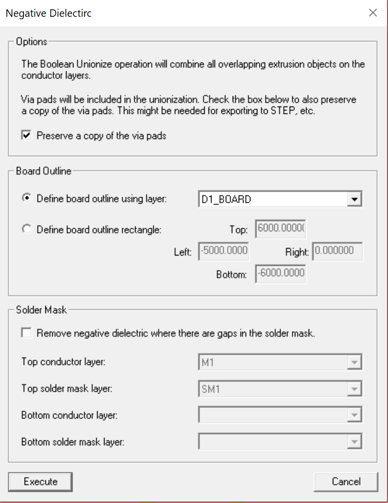
Once you have the correct settings, click on Execute. This will generate the two negative dielectric layers and place them in your 3Di database.
Then save this 3Di database under the filename of your choice. Say pcb_stackup.3di.
2. Create a Separate 3Di for each Layer
Because of the way that Abaqus imports STEP, we will need to create a separate STEP file for each "layer". We do this by first creating a separate 3Di file for each layer.
Do this by turning off all layers except the one you want to export, then use the File | Export | Visible menu option to save the visible layer to its own 3Di file. For example, if you have turned off all layers except for M1, export it and call it M1.3Di. Do that for M2,D1,D1_BOARD, M1-1 and M2-2. You should have 6 3Di files now, one for each layer.
3. Exporting a STEP file for each Layer
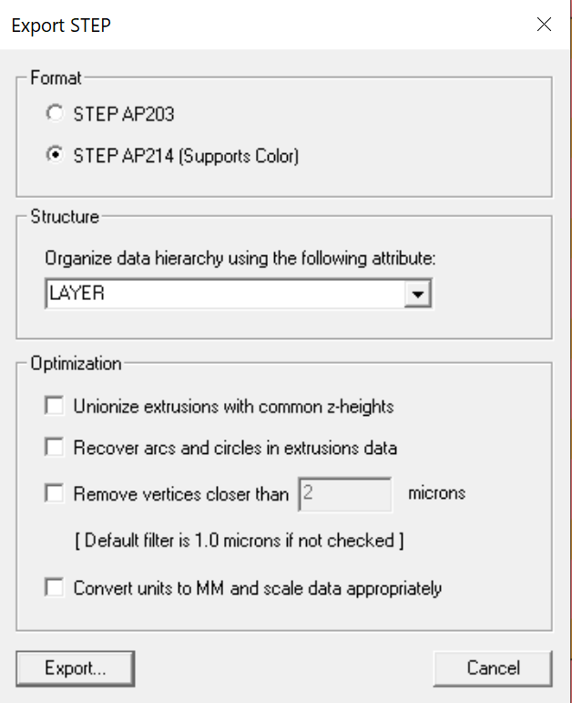
Now that you have your 6 individual 3Di files, export STEP from each one. Open the file, go to the Export | STEP dialog and export it. Repeat until you have 6 STEP files.
On the Abaqus Side
4. Create Part from STEP File
On the Abaqus side, we are going to import each STEP file and create a "part" for it. We will use the Part Filter: Import All Parts and also Combine into a single part. So when we import the STEP file M1.STEP we should get a part called M1.
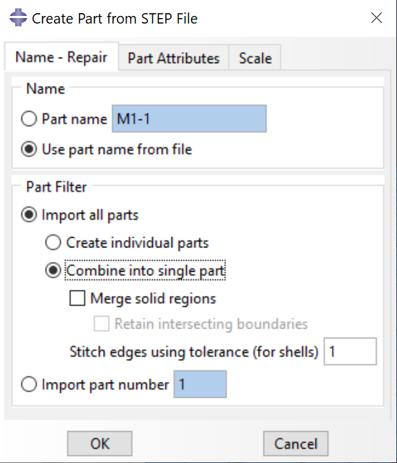
We will repeat this over and over again until we have all 6 parts defined.
5. Creating an Instance in Abaqus
We've got our parts in Abaqus and now we need to actually "place" them. Fortunately, the way the STEP data (and thus the parts) were created, each part's reference point is 0,0,0 but the geometry data is positioned as in the original stackup. So there is no need to know where to place the instance.
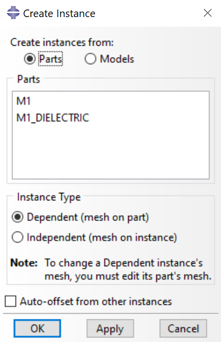
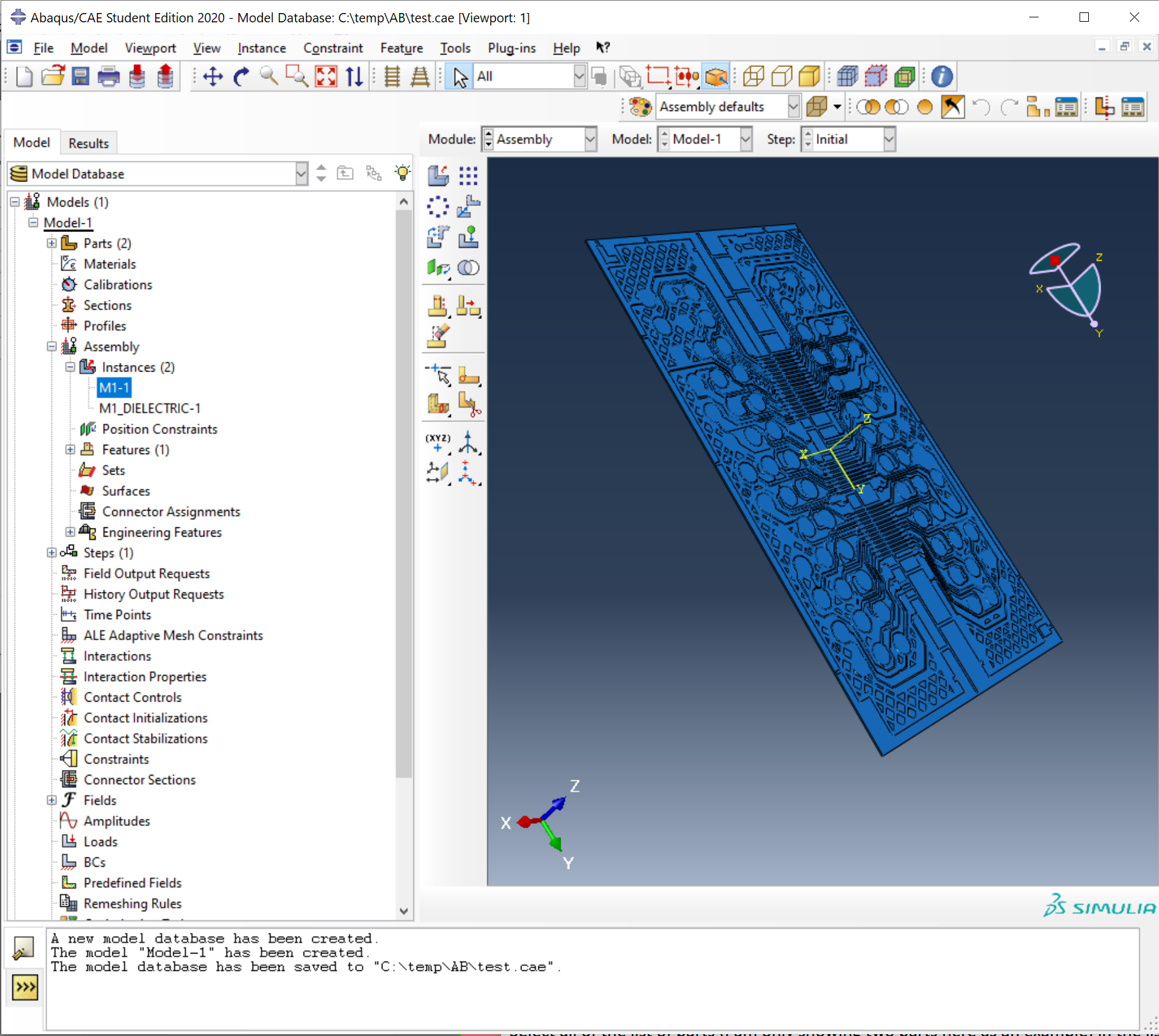
(The screen shot only shows a couple of parts for simplicity but for the whole board you should have all 6 parts in the list)
Once you click Apply or OK, Abaqus will now have a model of your board. And each "layer" is segregated into its own "part" so you can assign electrical properties such as conductivity and dielectric constant on a per part basis.
