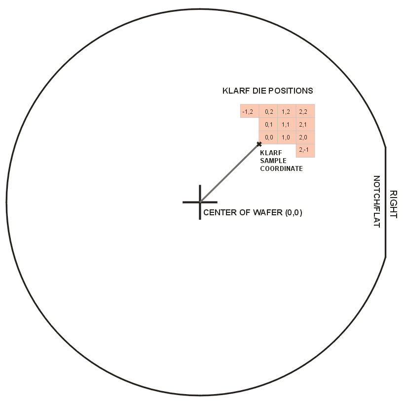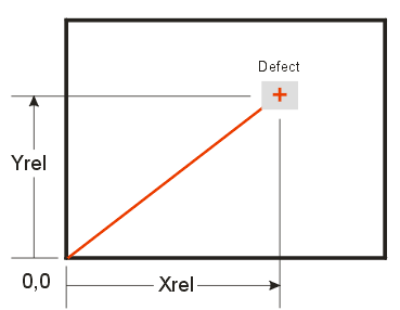
KLARF is KLA Tencor's defect reporting file format. It contains elements of a wafer map but it also includes data about the defect's location within each device—something other map files don't support. Further, the KLARF file includes pointers to bitmap files which are images of the defect. So KLARF is a bit of a hybrid database.
The KLARF file is divided into five major sections.
1. HEADER
this section contains general information about the substrate. Important parameters in this section are:
Sample Center Location - a reference coordinate where the 0,0 die has it's origin.
Die Pitch - the pitch between the die in the array.
Die Origin - coordinates of the lower left corner of the die.
Notch/Flat Location - where the notch or flat of the wafer is located - i.e. top, bottom, left or right.

OrientationMarkLocation DOWN;

DiePitch 3.5717153320e+003 3.3786257324e+003;

DieOrigin 0.000000 0.000000;

SampleCenterLocation 1.4683145313e+005 1.3981967188e+005;
using this information, one can determine where a device is located when given the array index values.
2. CLASS LOOKUP
This is a table of index numbers. Each index number is associated with a description of a defect. The DEFECT section will reference the index number. Note: we have encountered KLARF files with more than 256 entries in the CLASS LOOKUP table. Since each entry maps to a bin code in other map formats and since other map formats can hold a maximum of 256 bin codes, this can cause a problem.
0 "Alignment Failure"

1 "New Defect Class 1"

2 "New Defect Class 2"

3 "Chip Edge Imported

4 "Chip Inside Imported

5 "Ink Dot Inspection Defect

6 "Frontside Defect

7 "Kerf Defect

8 "Measurement Failure

9 "Alignment Failure

10 "ILD Peel Off"

11 "Saw Extra/ Saw Defect"

12 "Crack Die"

13 "Hairline Chipping Big"

14 "Saw On Die/Shift"

15 "Not Separated/Not Complete Dicing"

16 "Missing Die"

17 "Top Side Chipping"

18 "Probe Damage"

19 "Die Backside"

20 "Small Poke"

21 "Frontside Defect"

22 "Stain/FM On Pad"

23 "Stain/FM On Die"

24 "Corner Die Chipping"
If we were converting the KLARF file to a MAP file, we would likely assign each of these defects to a bin code. Most MAP files support up to 256 bin code definitions. (At least one bin code must be reserved for "NULL" positions which KLARF does not have.) KLARF also does not have a bin code reserved for PASS devices.
3. INSPECTION TEST
A KLARF file may contain a single inspection test or multiple tests. We recommend that a separate MAP file be generated for each inspection test.
InspectionTest 1;4. SAMPLE TEST PLAN
After the Inspection Test has been defined, it will be followed by SAMPLE TEST PLAN. Our understanding is that this is a list of all the devices that have been tested. Each line in the list is the X,Y logical coordinates of the device (not physical coordinates)
SampleTestPlan 5411

29 0

30 0

31 0

32 0

45 2

46 2

47 2

48 2

49 2

50 2

51 2
5. DEFECT RECORD
Defects discovered are listed in this section. The columns of this section can vary and the first line defines the meanings of each column. Note that the same device may have multiple defects - either the same defect in different locations of the device or different defects.Let's analyze a typical defects section.
DefectRecordSpec 17 DEFECTID XREL YREL XINDEX YINDEX XSIZE YSIZE DEFECTAREA DSIZE CLASSNUMBER

TEST CLUSTERNUMBER ROUGHBINNUMBER FINEBINNUMBER REVIEWSAMPLE IMAGECOUNT IMAGELIST;
17DEFECTIDXREL YRELXINDEX YINDEXXSIZE YSIZEDEFECTAREADSIZECLASSNUMBERTESTCLUSTERNUMBERROUGHBINNUMBERFINEBINNUMBERREVIEWSAMPLEIMAGECOUNTIMAGELISTNow let's analyze a defect entry in our sample file to see how it makes sense. Each defect is preceded by the keyword DefectList.
DefectList

327

3.4916440430e+003 3.2954443359e+003

57 12

16.998291 16.990662

288.812211

1.6990661621e+001

17

1

0

0

0

0

1

1

1

0 ;

TiffFileName

TR7U5303.05_Ceres_256993787_1.jpg;
keyword at beginning of list
defect ID

defect location relative to die 0,0

die position in the array

defect dimensions (X,Y)

defect area

defect size

defect index: 17= Top Side Chipping

inspection test 1


image count

image list


name of image file that shows the defect
Converting a KLARF file into a generic map file requires that we ignore some of the information in the KLARF file as there is no equivalent in a map file.
Images
KLARF files often refer to images in the DEFECT RECORD section. There is no provision for images or even references to image files in a standard map file so this information is dropped.
Relative Position of the Defect
There is really no provision in a map file (except perhaps for SEMI-E142 ) to include the relative position of a defect within an individual die. All we can do for a given die is to assign it a bin code (from the CLASS LOOKUP table), a bin quality (typically FAIL) and a bin description (the text associated with the CLASS LOOKUP)

Multiple Defects on a Single Die
KLARF can report multiple defects on a single die. These might be the same defect class or different defect class. However a MAP file can only assign a single bin code to each die. In the case of multiple defects, a conversion to map format will only be able to use one of them. Artwork's converter uses the first defect and ignore subsequent defects on the same device.
Inspection Test
Each Inspection Test generates a separate map file.
Sample Test Plan
All devices listed in the Sample Test Plan are assumed to be PASS (GOOD) devices unless they are later listed in the DEFECTS RECORD section.
The Xindex,Yindex is used to identify a failed die and the bin code is determined by the CLASS. The bin code is assigned from the first defect encountered for that device. The TEST parameter is used to determine whether this defect belongs to the map being generated.