
July 20, 2018
Steve DiBartolomeo
Artwork Conversion Software, Inc.
SECS II Wafer maps can be created in one of three formats; row, array, and coordinate. The Electroglas prober supports only the ROW FORMAT since it is more condensed than the others. We'll show some ROW FORMAT data along with the physical layout.
The concept of the null bin is not used in ROW FORMAT. Instead the map goes row by row and includes the coordinate of the first die in the row and the number of die that follow. After this information is an array of bin codes for each of the die.
ORLOC (Origin Location)
There are four possible values: 1 (UR), 2(UL), 3(LL) 4(LR)
Reference Point in SECS coordinates
X and Y array position assigned to the reference device.
Once you have these two pieces of information you can then assign all the other devices in the map their proper array positions.
Let's look at the following excerpt from a Wafer Map
21 01                             Origin Location, 1 Byte
01                          ,     Upper Right

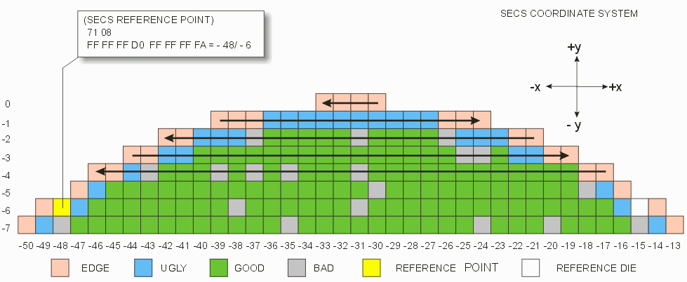
71 08                             Ref. Point (SECS), 8 Bytes
FF FF FF D0  FF FF FF FA          x=-48, y=-6

71 08                             Ref. Point Prober, 8 Bytes
00 00 00 30  00 00 00 06          x=48, y=6

A9 02                             Row Count, 2 Bytes
00 45                       ,     69 rows

A9 02                             Column Count, 2 Bytes
00 40                             64 colums

21 01                             Process Axis, 1 Byte
01                                probed in coordinate quadrant 1


START OF MAP STREAM

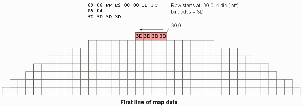
69 06 FF E2 00 00 FF FC           Row start coord x=-30, y=0, die count=-4 (to left)
A5 04                             bin codes for 4 die to follow
3D 3D 3D 3D                       3D=Edge Die

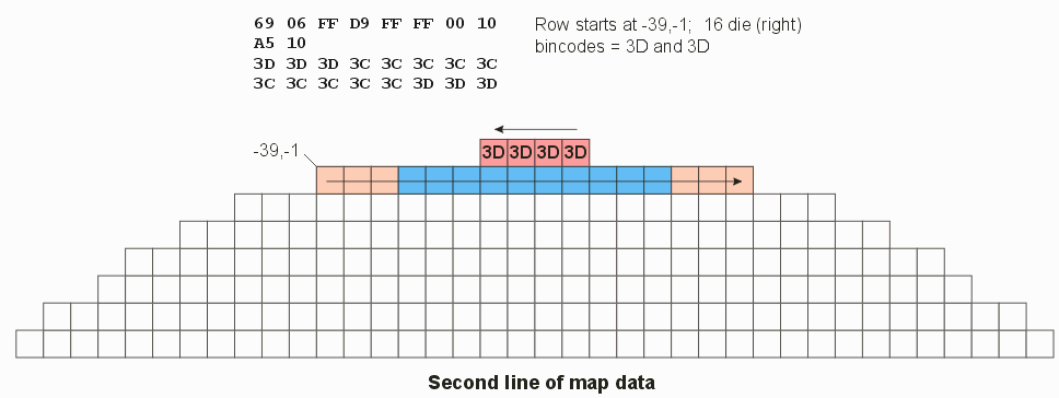
69 06 FF D9 FF FF 00 10           Row start coord x=-39, y=-1, die count= 16 (to right)
A5 10                             bin codes for 16 die to follow
3D 3D 3D 3C 3C 3C 3C 3C           3C=Ugly Die
3C 3C 3C 3C 3C 3D 3D 3D

69 06 FF EB FF FE FF EA           Row start coord x=-21, y=-2, die count= -22 (to left)
A5 16                             Bin codes for 22 die to follow
3D 3D 3C 3C 3C 00 01 01           00=Bad Die, 01=Good Die
01 01 00 01 01 01 01 01
00 3C 3C 3C 3D 3D

69 06 FF D4 FF FD 00 1A           Row start coord x=-44, y=-3, die count= 26 (to right)
A5 1A                             Bin codes for 26 die to follow
3D 3D 3C 3C 01 01 01 01
01 01 01 01 01 01 01 01
01 01 01 00 00 01 3C 3C
3D 3D

69 06 FF EF FF FC FF E2           Row start coord x=-17, y=-4, die count= -30 (to left)
A5 1E                             Bin codes for 30 die to follow
3D 3D 3C 01 01 01 01 01
01 01 01 01 01 01 00 01
01 01 00 01 00 01 00 01
01 01 00 3C 3D 3D

69 06 FF D1 FF FB 00 20           Row start coord x=-47, y=-5, die count= 32 (to right)
A5 20                             Bin codes for 32 die to follow
3D 3C 01 01 01 01 01 01
01 01 01 01 01 01 01 01
01 00 01 01 01 01 01 01
01 01 01 01 01 00 3C 3D

69 06 FF F2 FF FA FF DC           Row start coord x=-14, y=-6, die count= -36 (to left)
A5 24                             Bin codes for 36 die to follow
3D 3E 3C 01 01 01 01 01           3E=REFERENCE POINT
01 01 01 01 01 01 01 01
01 00 01 01 01 01 01 01
00 01 01 01 01 01 01 01
01 3C 32 3D
If we now begin to "draw" the map, the first RSINF in the map file generates the row for Y=0.

The next RSINF generates the row for Y=-1

We continue to read each subsequent RSINF command until all the rows are processed.

The reversal of direction with each row is not mandatory. This data was generated by an EG prober and the map output follows the same order that the die were probed. However the SECS II specification does not mandate such a path -- it allows it.