The WWF Wafer Map Format
This format was defined by Texas Instruments almost 20 years ago and is widely used not only by TI but by a number of manufacturers of test and assembly equipment.
Orientation
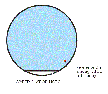
WWF wafer maps are always oriented with the FLAT or NOTCH down. Hence no parameter for the wafer flat location is needed. However if converting from a wafer map that has a flat on top, left or right, the data positions should be rotated as needed to produce output with the flat/notch down.

Reference Die
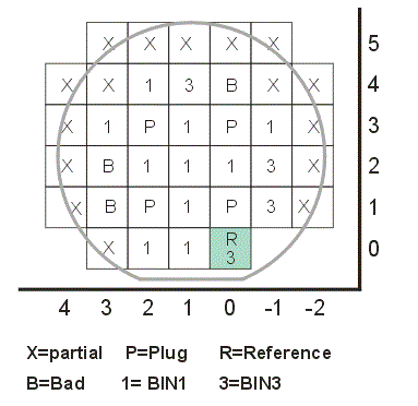
The reference die used to align the wafer on equipment is always assigned to the array position 0,0. You can see this in the sample below:

This does not mean that the reference die is located at the center of the wafer. It means that the reference die is assigned position 0,0 in the array and all the other positions are relative to this one; therefore there will always be negative array coordinates for X and Y.
WWF Header Syntax
Below you will find a summary of the keywords used in the WWF format:
| Keyword | Required? | Notes |
| FACILITY | Yes | Fab Facility ID; up to 8 characters. |
| LOT | Yes | Lot ID - 7 numerals |
| DEVICE | Yes | FAB type device - 1-14 characters |
| WAFERS | NO | Number of Wafers |
| USER | NO | User string - up to 20 characters |
| PROBE_FACILITY | No | probe facility ID - up to 14 characters |
| X_SIZE | Yes | Die X dimension. |
| Y_SIZE | Yes | Die Y size |
| UOM | No | Units of Measure 2 to 4 characters |
| PIN_ONE | No | Pin One Orientation 3 numerals |
| BIN_NAME.bb | Yes | Bin bb type and Name. Alpha Numerical 1-16 |
| STATUS | Yes | Status of Map; Alpha Numerical 1-4 chars |
| SCRIBE | Yes | wafer ID info - alpha numerical 1-8 chars |
| DIE_DESIGNATOR | No | Die Designator; alphanumeric 1-20 chars |
| WAFER_SIZE | Yes | Wafer Size in MM; Numeric 3 digits |
| LAYOUT | No | Wafer Layout Name; alphanumeric 1-14 chars |
| SHOT_MAP | No | Shot map coordinates. Alpha Numeric String. No limit |
| PLUG_MAP | No | Plug map coordinates. Alpha Numeric String. No limit |
| PARTIAL_MAP | No | partial (die) map coordinates. Alpha Numeric String. No limit |
| WAFER_ID.xx | Yes | Wafer ID. Must follow specific naming rules |
| FAB_ID.xx | No | Optional ID. |
| NUM_BINS.xx | Yes | Number of bins for wafer.xx. Numeric 2 digits. |
| BIN_COUNT.xx.bb | Yes | for wafer.xx number of die in bin.bb; Numeric, 2 digits. |
| MAP_XY.xx.bb | Yes | Wafer.xx map for bin.bb. AlphaNumeric String. No limit |
| END. | Yes | End of the Wafer Map File |
Bin Classes
There are a number of different die types and these are placed into bins. The rules for which die types are assigned to which bins are summarized in the table below:
| Bin Number |
Category | Notes |
| 01 | GED (good electrical die) | A whole patterned die and probed. Inward of the EEZ (edge exclusion zone). |
| 02-06 | Multi-Bin or Outlier GED | A whole patterned die probed and located inside of the EEZ (edge exclusion zone). |
| 07 | Reserved | Do not create bin 07. |
| 08 | Plug Die | Whole Die used for Alignment or Test. Not in the EEZ. |
| 09 | Reject Die | Whole Die probed inward of the EEZ. |
| 10 | Edge Die | Whole or Partial Die. Touching or lying in the EEZ. Could also be a mirror die, alignment marker, test die, or Ghost die. |
| 11-15 | SWR Die | Whole patterned die; inward of EEZ and probed. May be a reference die. |
| 16-17 | Reserved | Do not generate any bin codes in this range. |
| 18 | Mirror Die | Mirror surfaced die positioned either completely or partially in the EEZ. Cannot be a reference die. |
| 19 | Ghost Die | located either completely or partially in the EEZ. Cannot be a reference die. Unpatterned. |
| 19 | Unbuildable Die | whole patterned die located inside of the EEZ. Can be a reference die. G required. |
Header
FACILITY=OEMNAME               Facility ID
LOT=99XXX.1                    Lot ID
DEVICE=CMD252EUBMB4            Device ID
WAFERS=01                      Number of Wafers in this file
X_SIZE=123.228                 Die Size in X (units appear to be mils
Y_SIZE=123.228                 Die Size in Y (units appear to be mils
SCRIBE="BOTTOM,15,NTRL,FAB"    Location of scribed data?
WAFER_SIZE=150                 Wafer diameter in mm
STATUS="PROD"                  Status
USER="NOINK"                   User or user defined info
BIN_NAME.01="G,PASS"           Bin category
BIN_NAME.09="FAIL"             Bin category
This is followed by a section called a shot map. This appears to be a listing of all die - perhaps those present from the reticle shots. Notice that for each Y row (ranging from -21 to 20) there is a "list" of X locations.
SHOT_MAP="Y-21 12/31 Y-20 10/33 Y-19 9/34 Y-18 8/35 Y-17 7/36
Y-16 6/37 Y-15 5/38 Y-14 4/39 Y-13 3/40 Y-12 3/40 Y-11 2/41 Y-10 2/41 Y-9 1/42
Y-8 1/42 Y-7 1/42 Y-6 0/43 Y-5 0/43 Y-4 0/43 Y-3 0/19 24/43 Y-2 0/19 24/43
Y-1 1/19 24/42 Y0 1/19 24/42 Y1 1/42 Y2 1/42 Y3 1/42 Y4 1/42 Y5 1/42 Y6 1/42
Y7 2/41 Y8 2/41 Y9 3/40 Y10 3/40 Y11 4/39 Y12 5/38 Y13 5/38 Y14 6/37 Y15 7/36
Y16 8/35 Y17 10/33 Y18 11/32 Y19 13/30 Y20 16/27"
Now the wafer is identified, the number of bins is declared and a BIN (previously defined) referred to. That is followed by all the die positions belonging to this bin.
WAFERID.01=LG991-01-E4
NUM_BINS.01=02
BIN_COUNT.01.01=01313
MAP_XY.01.01="Y-21 12/18 20/28 30/31 Y-20 10/12 15/33 Y-19 9/34
Y-18 8/13 16/35 Y-17 7/13 16/22 24/27 29/35 Y-16 6/13 15/37 Y-15 5/8 10/13
16/31 33/37 Y-14 4/13 16/39 Y-13 4/13 16/26 28/40 Y-12 4/12 16/40 Y-11 2/5 7
9/12 16/41 Y-10 2/8 10/13 16 18/24 26/37 39/41 Y-9 1/13 16/42 Y-8 1/13 17/42
Y-7 2/13 17/25 27/42 Y-6 0/13 17/43 Y-5 0/13 18/43 Y-4 0/14 17/43 Y-3 0/7 9/14
17/19 24/43 Y-2 0/14 17 19 24/41 43 Y-1 1 3/5 7/11 13/17 19 26/29 31/42 Y0 2/10
17 36/42 Y1 1/11 23 27/31 38/42 Y2 1/2 4/10 14 19 21/22 24 26/42 Y3 1/2 4/10
12/21 23/32 35/42 Y4 1/2 4/14 16/19 21/29 31 33/42 Y5 1/2 4/42 Y6 1/2 4/17
19/23 25 27/42 Y7 2 4/25 27/41 Y8 2/17 19/41 Y9 4/40 Y10 4/13 15/18 20/23 25/29
31/36 38/40 Y11 4/31 33/39 Y12 5/12 14/38 Y13 5/25 27/38 Y14 6/16 18/37 Y15 7/9
11/29 31/34 36 Y16 8/16 18 20/27 29/35 Y17 10/33 Y18 11 13/29 31/32 Y19 13
15/21 23 25/30 Y20 16/19 21/24 26/27"
The next bin is enumerated followed by all the die positions belonging to this bin.
BIN_COUNT.01.09=00165
MAP_XY.01.09="Y-21 19 29 Y-20 13/14 Y-18 14/15 Y-17 14/15 23 28 36
Y-16 14 Y-15 9 14/15 32 38 Y-14 14/15 Y-13 3 14/15 27 Y-12 3 13/15 Y-11 6 8
13/15 Y-10 9 14/15 17 25 38 Y-9 14/15 Y-8 14/16 Y-7 1 14/16 26 Y-6 14/16
Y-5 14/17 Y-4 15/16 Y-3 8 15/16 Y-2 15/16 18 42 Y-1 2 6 12 18 24/25 30 Y0 1
11/16 18/19 24/35 Y1 12/22 24/26 32/37 Y2 3 11/13 15/18 20 23 25 Y3 3 11 22
33/34 Y4 3 15 20 30 32 Y5 3 Y6 3 18 24 26 Y7 3 26 Y8 18 Y9 3 Y10 3 14 19 24 30
37 Y11 32 Y12 13 Y13 26 Y14 17 Y15 10 30 35 Y16 17 19 28 Y18 12 30 Y19 14 22 24
Y20 20 25"
The file is closed with an END.
END.
