In this app note we show how to use WMBatch to split a very large map file for a 300 mm wafer into four smaller map files. This particular requirement occurs when trying to process 300 mm wafers on 200 mm equipment. In some cases one has to physically slice the 300 mm wafer into 4 pieces; in other cases the wafer fits on a large chuck but the equipment's ability to move across the full 300 mm wafer is limited to only 200 mm. In either event, in order to process the entire wafer one needs to create 4 separate map files representing the 4 quadrants of the wafer.
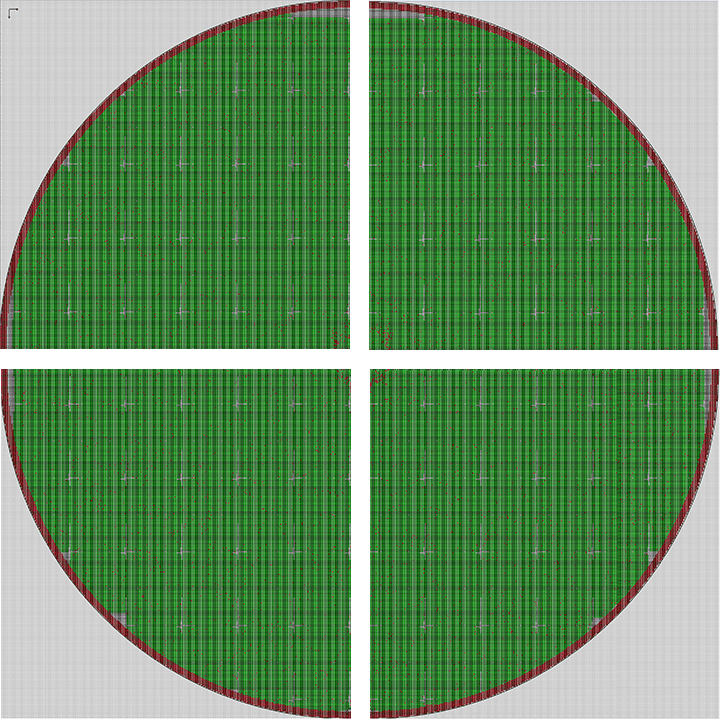
Our input map file is in IBIS format and it looks like this when the entire wafer is viewed:
Wafer diameter = 300 mm
Device Size = 0.5mm x 0.51 mm
Columns = 599
Rows = 588
Good Devices = 254,227
Origin (0,0) = Upper Left

We want to slice the wafer map into quadrants as shown here:
New Sections = 150 x 150 mm sq.
Device Size = 0.5mm x 0.51 mm
Columns = 300/299
Rows = 294

In addition to the standard directives such as open and save, we are going to utilitize a couple of special directives:
this directive fills all device locations with a user specified bin code outside the specified region. The regions are specified by the corner array coordinates.
so if we write:
wafer fill outside 0,0,298,293
then everything outside that region (the UL quadrant) will be filled with NULL bin codes.


this directive removes empty (i.e. only containing null bincodes) rows and empty columns
so if we write:
wafer delete rowswafer delete columns
Then the map file is trimmed to just the contents of the UL quadrant. We can save this as a new wafer map.

By combining these two directives and specifying the correct regions, we can create 4 separate wafer maps; each which fit on 200 mm equipment.
split_one_into_four.txt
# Example command file: split_one_into_four.txt

# Input is a large IBIS map;

# sliced into quarters - UL,UR,LL,LR - output 4 separate map files

# Input Map has 588 rows 599 columns

# Steve DiBartolomeo, Artwork Conversion Software Inc.

# December 18, 2021; revised May 13, 2022


# first step is always to define input_dir and output_dir


input_dir  "E:\cad_data[2]\wafer_map_evals\EXAMPLES\SPLIT24MAPS\input"

output_dir "E:\cad_data[2]\wafer_map_evals\EXAMPLES\SPLIT24MAPS\output"


# now open our source map file (must indicate what format it is)


open dense_300mm_wafer.map format IBIS


# this map has a lot of un-used bin code defns. We are going to delete them.


bin delete unused


# now we are going to fill everything outside the selected window with null bin codes

# coordinates: left_col top_row right_col bottom_row [bin_code]

# [bin_code] is optional; if not present defaults to the NULL bin code


wafer fill outside 0 0 298 293


# now we are going to trim away all the empty rows and columns that result from the fill operation


wafer delete rows

wafer delete cols


# next we save output to the same format also naming the quadrant


save dense_300mm_wafer_UL.map


# in order to do the next quadrant we have to reload the wafer data since

# our first operation "modified" all the device bin codes except for those

# in the first quadrant; the wafer reload command does this

# remember our count starts at 0,0 so mid point of 588 is 588/2 - 1 = 293


wafer reload

bin delete unused

wafer fill outside 299 0 598 293

wafer delete rows

wafer delete cols

save dense_300mm_wafer_UR.map


wafer reload

bin delete unused

wafer fill outside 0 294 298 587

wafer delete rows

wafer delete cols

save dense_300mm_wafer_LL.map


wafer reload

bin delete unused

wafer fill outside 299 294 598 587

wafer delete rows

wafer delete cols

save dense_300mm_wafer_LR.map