
|
Converting a List of Vertices to GDSIIConsider the requirement to convert a list of polygon vertices into a GDSII file. For the moment, let us assume that the vertices are ordered and that no illegal polygons are included -- that is, the list provides them in the proper order needed to circumscribe a boundary without self intersection (we will discuss the non-ordered case later ...) The list may come from a variety of applications - for example, a routine that scans an IC mask, detects the edges and outputs the vertices of the edges or from a Visual Basic program that generates shapes from user provided parameters. Step 1 - Formatting the Vertex ListThe first step is to format the vertex list into the ASCII format accepted by Artwork's ASCII2GDS program. (Of course, one could write a custom program that accepts the list format directly, but we would prefer to "bolt" together existing tools ...) An example of Artwork's ASCII format is shown below along with annotations in italics:
LIBRARY BOX.GDS unit:UM grid:1000   defines libname, unit/resolution
STRUCT TOP                          starts a structure definition
                                    from here on you create a boundary for each polygon

BOUNDARY 0 0                        beginning of a boundary (lay=0)
0 0                                 xy coord
1000000 0                           xy coord
1000000 1000000                     xy coord
0 1000000                           xy coord
0 0                                 xy coord; last coord must = first
ENDEL                               ends the element definition

BOUNDARY 0 0                        beginning of a boundary (lay=0)
15000 15000
985000 15000
985000 985000
15000 985000
15000 15000
ENDEL

BOUNDARY 0 0
150000 150000
850000 150000
850000 850000
150000 850000
150000 150000
ENDEL

ENDSTR                             ends the structure definition
ENDLIB                             ends the library definition
|
Step 2 - Running the ASCII to GDSII Conversion |
||
|
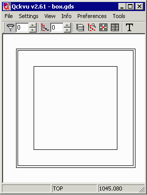
The above list contains 3 square boundaries, one inside the other. We can convert this file to GDSII stream using the ASCII2GDS program and the following command line: ascii2gds.exe box.txt box.gds The resulting file, box.gds, will appear as shown in the GDSII viewer snapshot at right. |
 Fig 1: box.gds displayed in outline mode. |
|
|
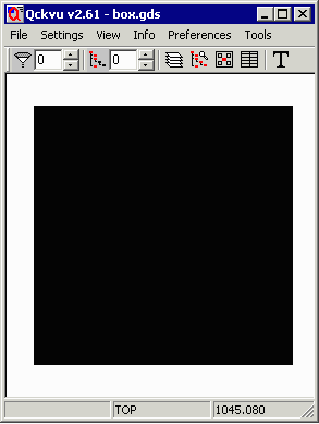
Because each boundary is "filled" in GDSII, the actual metallized region will appear as shown at right. You will notice that the two inner boundaries are covered by the larger of the three boundaries. The problem is that we don't want the metal to look like that -- we are expecting that each boundary defines a change in polarity. |
 Fig 2: box.gds displayed in fill mode. |
|
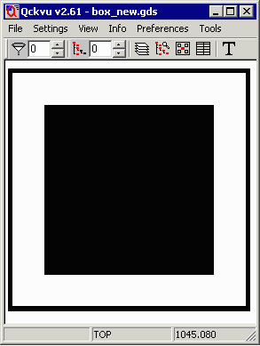
We want the metallized area to look like the snapshot at right: How are we going to achieve this result from the list we have which only contains the vertices of the boundaries and has no intelligence about the relative relationship between boundaries? |
 Fig 3: How we want the mask to look. |
| Next - Dembedding Routine Creates Correct Polarity ... |