Reversing a GDSII file - Convertion to PG
When creating a drawing, sometimes it is necessary to create polygons with angles less than 90 degrees. For most file formats such as GDSII, MEBES, etc... this is not a problem. But, when transferring to PG format, it can create serious design flaws because the program cannot put a flash at a corner that has an acute angle and will instead leave a void.
First, if you are creating a drawing for Pattern Generator, we recommend avoiding acute angles as much as possible. However, if there is no way around it, the following will help get cleaner results when translating from GDSII to PG.
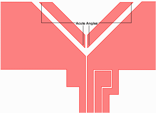
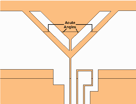
As you can see from a close-up view of this GDSII drawing, there are some acute angles present.
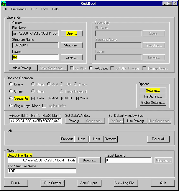
We'll run the file through QckBool to create a reversal which is necessary for this specific design. There are also some special settings we'll use to reduce the number of acute angles in the drawing and avoid small geometries that are less than the minimum flash size that the PG machine can handle.
We've selected the file name and the layers 0-1 which will create the reversal. Layer 0 of this drawing is simply an outline around the entire circuit while layer 1 is the circuit itself in positive mode. In the Boolean Operation section we've chosen chosen Sequential since we are subtracting one layer from the other.. The Output File is set to go to the same directory where the original file is located. Now we'll open the Settings Menu.
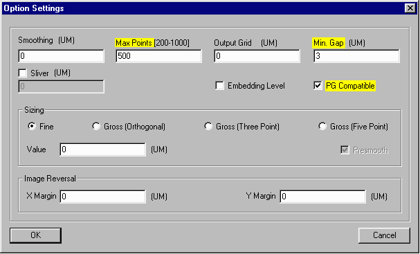
From the Settings Dialog we've set the Max Points to 500 because the GDSII to PG translator has a limit on the number of vertices per polygon which it supports.
The Min. Gap value we've chosen is 3 um, however this number should
equal the minimum flash size allowed by your particular machine. It usually ranges from 1 to 5 um.
Lastly, we've selected PG Compatible which will tell QckBool to try to create boundaries with no acute angles
so it will be converted accurately by the pattern generator translator.
The reason we want to avoid acute angles is because the Pattern Generators can only image rectangles so
there is always going to be a small approximation when dealing with acute angles.
The error in the approximation is the size of the minimum flash the PG machine can handle.
After running the drawing through QckBool we've created a new GDSII file. All the filled polygons in the original file are now clear. The program has tried to clear up the angles which were less than 90 degrees by creating new polygons with cutlines. Still, there are some acute angles that could not be avoided.
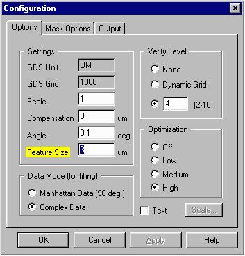
Now, we'll open the GDS2PG translator to begin the conversion process. We've opened the Configuration Menu and have set the Feature Size to 3 um, (this should be set the minimum flash size on your particular machine). The other default option settings will work fine.
When we run the translation the following PG file is created from the reversed GDSII drawing. Notice the voids in the areas where the acute angles are located.

Let's zoom in for a closer look.
