Removing Cutlines to Create Reverse Polarity
The Problem
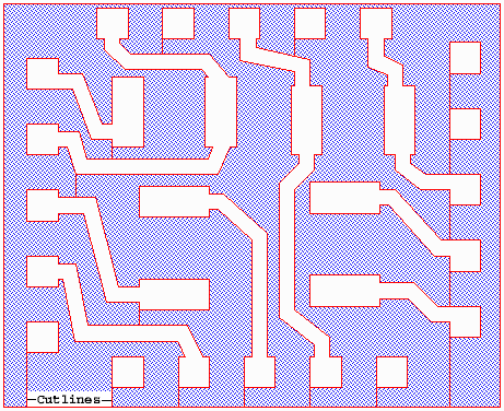
Below we have a GDSII drawing which contains a large complex re-entrant boundary. This is a common way of creating a void within a metal area. However some CAD systems are unable to import or process any boundary that touches itself. Before you can send such a GDSII file to some programs you need to convert these re-entrant boundaries. QckBool enables one to write a new file where additional layers are created as needed to hold the void boundaries.
The program can remove the cutlines in drawings such as this and give the user independent bounaries.

The Solution
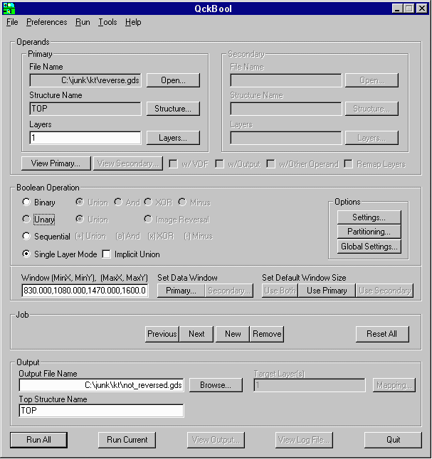
Start QckBool and in the Primary Operands section, open the file called reverse.gds.
In the Output field define a new name: not_reversed.gds.
Set the Boolean Operation section to Single Layer Mode, because the source data is all on one layer.

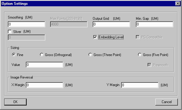
Open the Option Settings dialog box and check the Embedding Level option. This will convert all of the re-entrant polygons by creating new layer levels for each polarity reversal.

CLICK on the Run Current button at the bottom of the Main Menu.
The Status Menu will appear asking if you would like to see the status of all the files. CLICK Yes.
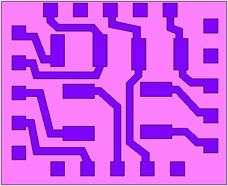
A log file will appear with the status of the job. Close this file and GDSVU will open the new file (not_reversed.gds).

The new drawing has two layers of data separate from one another. If the user wanted to get the reverse polarity of the original drawing, the first layer could be discarded.