
Gbrunmgr, a program that controls the gbrunion library, is extremely powerful and has an extensive number of options and controls as well as the ability to produce a number of different output formats. So we can't cover every possible command line possibility. We'll try to show the more common operations in the following examples.
When using the command line, best practice is to fully define the path as part of the filename. If you use relative path or no path then you risk your script or batch file breaking.
Current Directory - on Windows the batch/scripting variable for the current directory is %CD%. I typically like to place and execute my batch files from a directory which also holds the input data. I will use that convention in these examples.
Quoting of Directories - if a directory or file name has a space or special character in it the entire command should be surrounded by double quotes. i.e
Command Line Breaks and Indents - In all the examples below you will see "breaks" in the command line. This is only for readability.
Executable - In all examples below I've used gbrunmgr64.exe where normally I would use a full path such as
We want to convert a rectangular window of our file into a nice clean DXF that will be used for documentation purposes. We want a clean DXF layer even if the Gerber file has many internal layers. We will maintain the same units and coordinates as the Gerber input file.
gbrunmgr64.exe                                 executable
   "%CD%\icsxseed.gbr"                       input RS274X file (units=inch)
        "-out:%CD%\output\icxseed.dxf"       output DXF file
            "-wdir:%CD%\working"             working directory

             -window:3.5,6.6,4.85,7.9        LLx,LLy,URx,URy to extract
               -outputtype:dxf               output file format
                 -polyformat:leonov          polygon format
                    -arcsag:0.0002           arc smoothness
Below you can see our Gerber input file and the resulting DXF output of the window we selected:
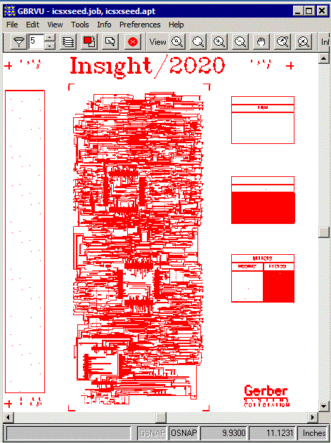
The source Gerber file: icsxseed.gbr (example directory)
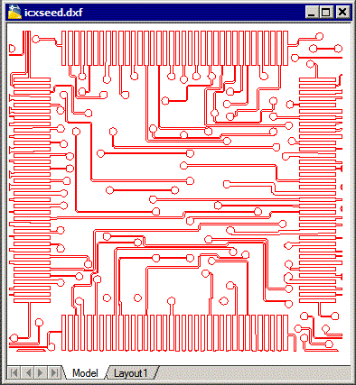
The clipped DXF file displayed in AutoCAD
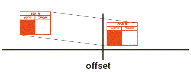
We will start as in Example 1 by clipping out a rectangular window -- but then we will mirror the output (mirror_X) and then offset the coordinates to move the windows so that it's lower left is at 0,0. To do this, we'll add a new argument - xform. Note that since xform works on the output data, you don't have to worry about it affecting your clipping/extraction window which is done before xform.
gbrunmgr64.exe                      executable
 "%CD%\icsxseed.gbr"              input RS274X file
 "-out:%CD%\output\defect.dxf"    output file
 "-wdir:%CD%\working"             working directory

 -window:7.6,3.75,9.6,5.25        LLx,LLy,URx,URy to extract
 -outputtype:dxf                  output file format
 -polyformat:leonov               polygon format
 -arcsag:0.0002                   arc smoothness
 -xform:0,0,0,1,0,1,1,9.6,-3.75   output transformation
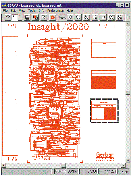
The rectangular window to extract
The xform flag
mirror_X:0, 0,0,1,0,1,1,9.6,-3.75
reverses the image but also places the results in the wrong quadrant.
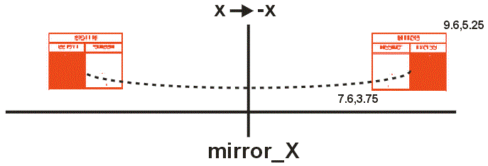
to get the data back so that the lower left of the window is at 0,0 we offset it by +9.6 in X and -3.75 in Y.
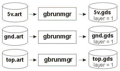
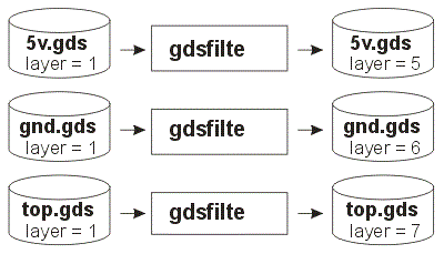
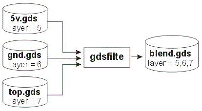
In this example we are going to convert multiple Gerber files into a single GDSII file maintaining layer seperation. To accomplish this is a 3 step process: 1) Convert each Gerber into its own GDSII 2)remap the GDSII layer to a unique layer 3) Merge all three GDSII files into a single multi-layer GDSII.
The gbrunion engine can only produce single layer GDSII. But we easily solve this with a multi-command batch file and the use of GDSFILT to remap the layers and then merge all three GDSII files into one..
Below is a three stage example which creates a multi layered GDSII output file. Note that in the actual command line there are no embedded CR/LF; they are only present here for clarity.
(1) Generate a GDSII file for each Gerber file
"c:\wcad\gbrvu64\artwork\gbrunmgr64.exe"
"d:\temp\5v.art"
"-out:d:\temp\5v.gds"
"-wdir:d:\temp"
-outputtype:gds_stream
-maxpoints:2000
-arcres:9
-silent
-singledlg


"c:\wcad\gbrvu64\artwork\gbrunmgr64.exe"
"d:\temp\gnd.art"
"-out:d:\temp\gnd.gds"
"-wdir:d:\temp"
-outputtype:gds_stream
-maxpoints:2000
-arcres:9
-silent
-singledlg


"c:\wcad\gbrvu64\artwork\gbrunmgr64.exe"
"d:\temp\top.art"
"-out:d:\temp\top.gds"
"-wdir:d:\temp"
-outputtype:gds_stream
-maxpoints:2000
-arcres:9
-silent
-singledlg
(2) Use GDSFILT to Remap Layers
c:\wcad\gbrvu64\artwork\gdsfilte64.exe
d:\temp\5v.gds
d:\temp\5v_lyr1to5.gds
=
-unixcmdline
-lyr1:5


c:\wcad\gbrvu64\artwork\gdsfilte64.exe
d:\temp\gnd.gds d:\temp\gnd_lyr1to6.gds
= -unixcmdline
-lyr1:6


c:\wcad\gbrvu64\artwork\gdsfilte64.exe
d:\temp\top.gds
d:\temp\top_lyr1to7.gds
=
-unixcmdline
-lyr1:7
(3) Blend the Resulting GDSII files into a Single One.
Now that we have each GDSII file with data on unique layers, we can "blend" all three files into a single multi-layer using the gdsfilt engine. There are different options when combining GDSII files, and blend is the option to use when the data structures are the same.
c:\wcad\gbrvu64\artwork\gdsfilte64.exe
d:\temp\5v_lyr1to5.gds
d:\temp\blend.gds
=
-unixcmdline
-blend
d:\temp\gnd_lyr1to6.gds
d:\temp\top_lyr1to7.gds
Note on GDSFILT Blend Syntax
The gdsfilte64.exe usage is as follows:
gdsfilte64.exe inputfile outputfile topstr [options]

where
  outputfile is the GDS output file name.

  only topstr and its dependents are output.
  If topstr is '=' then, the structure with
  the deepest tree is selected.

options can be some combination of:

   -unixcmdline      Perform GDSII scan (necessary in this context)
   -lyrM:N,...       Remap layer range M to N.
   -dtpM:N,...       Remap datatype range M to N.
   -mapM%N:m%n,...   Remap layer:datatype(s) M:N to m:n.
   -blend f1 f2 ...  fn  blend files f1, f2 ... fn with inputfile.