Ink Coverage
In order to provide a useful image or pattern, the droplets deposited by an inkjet must overlap to some extent. A typical ratio of overlap occurs when the pitch between droplets is approximately 1/3 of their diameter as shown below:
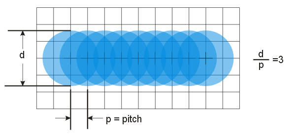
This ratio of diameter to spacing provides a fairly smooth "edge" but there is already significant ink build up due to droplet overlap.
If we attempt to reduce the droplet coverage by placing a droplet every other pixel we have a lot less droplet overlap but we also have much more ripple in the edge of the printed line.
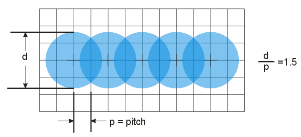
So there is a tradeoff between edge smoothness and ink coverage.
This is why the Inkraster program supports two separate coverage parameters - one for the "edge" of the figure being printed (where we would probably choose a high coverage to insure smoothness) and one for the interior of the figure where we can back off on the droplet overlap to prevent too much ink being deposited.
Coverage Controls
The InkRaster coverage controls are grid based - they don't take into consideration the actual diameter of the droplet. Therefore the user, when selecting the coverage values, should perform some basic calculations that include the droplet diameter.
Coverage = 1.0
Coverage = 1.0 means that every grid point has a droplet. This is how a standard rasterizer works. The actual ink density depends on the diameter of the droplet.
Coverage = 0.5
Coverage = 0.5 means that every other grid point has a droplet.
How are Non-Integral Coverages Generated?
Since we are restricted to placing a droplet on grid, how can we generate coverage values that are not multiples of the grid resolution? The solution is to use a Bayesian dithering algorithm. The downside to such dithering is that the local density is not constant. Therefore we recommend that non-integral values only be used for the interior; along the edge only select values of 1.0, 0.5, 0.3333 or 0.25.
Examples of Different Coverage Settings
To see what different coverage settings generate, we've ran a small batch file and varied the settings. The sample Gerber file, parallel.gbr, has lines and gaps = 4 mils (101.6 um) The assumed droplet diameter is 40 um.
c:\wcad\inkraster64\inkraster64.exe
     %CD%\parallel.gbr
         -out:%CD%\output\cov1_1.tif
            -workdir:%CD%\working
                 -dpi:2500
                      -droplet:40um
                         -compensate:1,0.5
                                 -coverage:1,1

alternate outputs
-----------------
-coverage:0.5,1
-coverage:0.333,1
-coverage:0.333,0.5
Here are the TIFF images (no droplet diameter effect is visible)
Coverage 1,1

As expected 1,1 gives us a droplet on every grid point.
Coverage 0.5,1
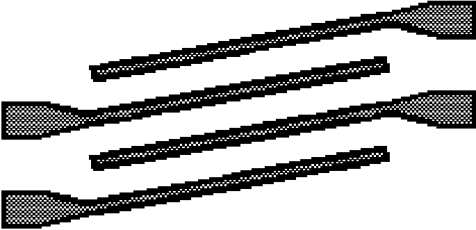
Here you can see what happens when the interior coverage = 0.5. You get a droplet on every other pixel.
Coverage 0.333,1
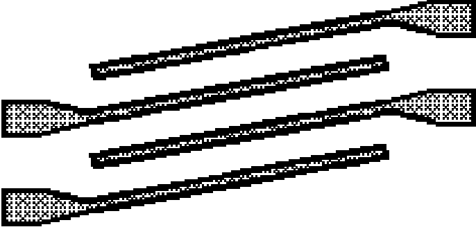
The coverage in the interior is reduced even further to 0.3333 while the edge remains set = 1.
Coverage 0.25,0.5
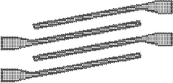
We've reduced the interior coverage to 0.25 and the edge coverage to 0.5. This may be too sparse to create a dense enough pattern on the substrate. How can you tell? Let's use Artwork's inkjet droplet simulator.
The simulator works by converting the TIFF bitmap back into Gerber. It places a flash of the correct diameter (40 um in this case) at each point where a droplet is placed. The resulting view simulates the ink coverage.
So apparently the ink coverage is still sufficient even at these lower coverage values to produce a correct image on the substrate.
