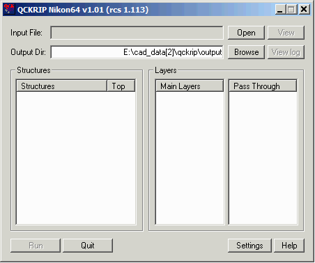
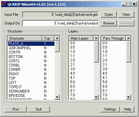
QckRip Settings Dialog
The settings dialog is divided into three tabs:
Settings - used to adjust program settings
Transformations - used to define transformations to the input data
Tiles - used to define the size and behavior of output bitmap tiling
Settings Tab
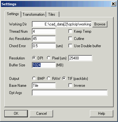
Working Dir
Specify a directory where temporary working files will be written to and read from. For large projects this will give fastest throughput if this directory is located on a solid state disk.
Thread Num
The number of concurrent raster threads to use. Do not specify a value larger than the number of CPU cores. Do not count hyperthreading as additional cores.
Arc Resolution
Not used for GDSII input.
Chord Error
Not used for GDSII Input
Keep Temp
If checked, temporary files written to the working directory are not erased when the rasterization is completed. Normally you would only check this option if debugging problems.
Cutline
Do not check this option -- it may not work correctly if transformations such as shear are applied.
Use Double Buffer
allocates a second buffer (per CPU thread) to allow simultaneous rasterizations and formatting/compression. You can use this if you have sufficient RAM. See reference section for an example of how RAM usage is allocated.
Resolution
Define the bitmap resolution. There are two ways to specify this value - DPI - dots per inch or pixel size in units of um. For example a 5080 DPI equals a 5 um pixel size.
Buffer Size
The amount of RAM allocated to the bugger which holds the bits used to compose a tile.
Output
Select one of the three output formats: Microsoft BMP (monochrome), RAW or TIFF with Packbits compression.
Base Name
The base name for the tiles that are produced. For example, if you specify a base name of "image" and the format is tiff, then the output files will be named image1.tif, image2.tif, image3.tif.
Inverse
If checked, digitized data is set to 0 and the non-digitized field is set = 1 in the output bitmap.
Opt Args
special arguments. Normally this is left blank except for debugging purposes.
Transformations Tab
The transformations tab enables the user to transform the input data.
Data Centered at 0,0
A fundamental assumption of the transformations listed here is that the source data is centered at 0,0. All transformations are centered about 0,0.
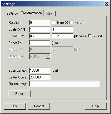
Rotation
Used to rotate the data around 0,0. Enter the value in degrees. Positive value of rotation goes in CCW direction.
Mirror X
Mirrors the data about the Y=0 axis.
Mirror Y
Mirrors the data about the X=0 axis.
Scale (X/Y)
Specify the scale factor. Separate scale factors can be applied to X and Y. Anchor point is 0,0.
Shear (X/Y)
Apply a Y or X (or both) shear. See reference for diagram.
Shear Tolerance
A small value (in units of microns) used to determine when circuits need to be exploded and sheared. The value is used to determine whether an instance of a cell is equivalent to other instances. If this value is set too small, each bitmap placement will require its own definition and the RIP will not run very quickly. The default value is 1.0. See reference for diagram.
Span Length
Used for repetition analysis of large circuits. See reference section.
Vertex Count
Used to limit the vertex count during repetition computations.
Optional Arguments
Normally left blank unless debugging the RIP.
Reset
Resets all transformations settings back to the default values.
Tiles Tab
It is not necessarily useful to create a single giant bitmap for a complete layout. At 0.5 um pixel the bitmap for a 300 mm x 300 mm mask is extremely large. It is much more common to produce a number of "tiles" that cover the image area. Tiles may butt up to each other or may overlap depending on the mask writer's architecture.
This dialog enables the user to control the size and behavior of the tiling.
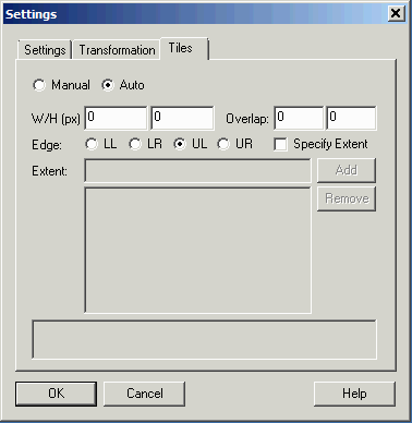
Manual vs. Auto
In manual mode the user specifies each tile. In Auto mode the user specifies a tile size and the program generates all of the times needed to cover the ROI (region of interest AKA data extents)
W/H in pixels
Specify the width and the height of the tile in pixels.
Overlap in pixels
Specify desired overlap along X and along Y in pixels. Default = 0.
Edge
Where to start the tiling process. One can choose from upper left, lower left, upper right and lower right.
Specify Extents
Check this box to enter the extents of the area to tile. (Note that extents are in user units - not in pixels)
See the reference section for examples of tile settings.
|
