 |
How to Approach the Rectangular to Polar ConversionIn our previous page we determined that there are approximately 1.34E12 pixels needed to drive the mastering machine. Now we have to come up with a way to do this in a reasonable amount of time using off-the-shelf hardware. (It might be useful to note that the original ETEC MEBES machines and the ATEQ laser pattern generators such as the Alta 3000/4000 used a custom array of hardware based rasterizers in order to pipe control data at sufficient rates to the exposure head.) |
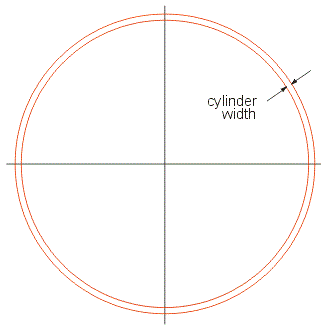
Option 1 - Rasterize First - then Convert the BitmapOne possible flow is to first rasterize your layout data to produce a Cartesian bitmap and then generate a polar bitmap from the Cartesian one.  We have experience in rasterizing GDSII to Cartesian (rectangular) bitmaps - so while this is a compute intensive step, we know that it can be done and that with reasonable hardware we can do it minutes - not hours. However the conversion from a Cartesian bitmap to a polar one appears to be more problematic. First, assuming we want to keep things off of disk, we would have to store the entire Cartesian bitmap in memory. We've already computed that this requires 158 GB. We'll also need the same amount of space in memory to store the polar version of the bitmap. So we need another 158 GB to do that. So our workstation will need more than 300 GB of RAM if we want to keep all operations off disk. I am going to assume that this is more memory than reasonable. Secondly, we would have to make 1.34E12 polar to rectangular computations. Even assuming there are a number of optimizations and lookups one can use to reduce this count, the sheer number of computations would insure run times measured in days and not minutes or hours. So let's set this aside and look at a second approach. Spiral Approximation by CylinderIn this approach we first divide the GDSII data into cylinders. The "wall" thickness will vary with the diameter of the cylinder. We'll clip the GDSII data that crosses the cylinder. Then we'll convert the Cartesian based boundaries into polar based ones. Finally we'll rasterizer the polar representation and the output will be sent to our polar bitmap. This is better described in pictures. |
|
Step 1 We cut the rectangular layout into many concentric "cylinders" |

|
|
|
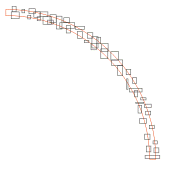
Step 2 We clip (and heal) all the boundary data that crosses the cylinder. (I've only shown a portion of the cylinder but in practice we would use the entire 360 degrees.) |

|
|
Step 3 We transfer our boundaries into a polar space. (the vertical axis is "r" and the horizontal axis is θ. |

|
|
|
Step 4 We now rasterize along θ in polar space. The resulting pixels can go directly into the polar bitmap. |

|
|
One advantage of this approach is that it can be coded to take good advantage of multiple processors. Unless the GDSII file is extremely large we can load it into memory and use a quad tree to quickly select boundary data that crosses our cylinder. A separate thread can be used to do the clipping and another thread to do the rectangular to polar conversion. Yet another thread does the rasterization. No formatting is really needed since we'll dump our pixel data uncompressed to the disk output. |