Chord Error and Arc Resolution
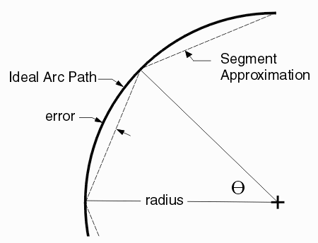
Many geometric operations used in CAD conversion and processing do not support arcs. In order to perform Boolean operations or to rasterize a layout we must first convert each arc (or circle) into a collection of line segments.

This has two main effects: a) we are now approximating the arc and b) we have to decide how many segments to use to make the approximation. The more segments, the less error but our database also gets bigger.
Ideally we know how much error we can accept; we'd like to use the minimum number of line segments necessary so that the maximum allowed error is not exceeded.
Arc Resolution vs. Chord Error
Artwork offers two separate "controls" for converting arcs into segments: Arc Resolution and Chord Error. Arc Resolution is conceptually simple but does not generally provide the best tradeoff between approximation error and database size. Chord error requires a bit more geometry but can result in a much smaller output database while keeping the approximation error to a known amount.
Arc Resolution
Arc Resolution is set in degrees: the number of degrees subtended by each segment.

Computing the Error
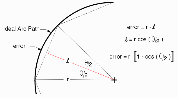
A little high school trigonometry will tell us the error. The error is a function of the radius - the bigger the radius the bigger the error:

Example
Imagine that your board design has many circles (pads) of the following different radii and that you have set your arc resolution equal to 9 degrees. We compute [1-cos(9/2)] = 0.0030826 then our error for the following radii is:
circle     max    number of
radius    error   segments
(mm)      (um)
0.1        0.31      40
1.0        3.08      40
5.0       15.40      40
If the allowable tolerance for your design is 5 um then the smaller pads will be OK but the larger pad will be out of tolerance. You would have to use a smaller arc resolution. So we set the arc res down to 5 degrees. Now [1-cos(5/2)]= 0.00095177
circle     max     number of
radius    error    segments
(mm)      (um)
0.1        0.095      72
1.0        0.95       72
5.0        4.75       72
Any problem here? Well, the main problem is that for the pads of 0.1 mm and 1.0 mm diameter 72 segments per pad is overkill. Ideally we would use less segments on the small pads and more segments as the pad diameter gets larger.
Chord Error
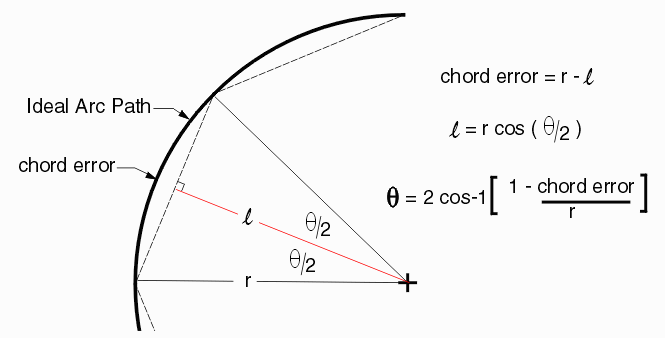
The chord error (also known in the past as arcsag) parameter enables the user to set the maximum allowable error; from that error value the program computes for each arc or circle exactly how many segments need to be used to meet (but not exceed) that error. This insures that the minimum number of segments is used for each arc approximation.
We only need to re-arrange our equation for the error to solve for the angle (and then we'll know how many segments are needed)

Example
Let's continue with the first example. Our tolerance (chord error) = 5 um (0.005 mm) and we have the same three radius pads. What does our table look like now?
circle     max    theta      number of
radius    error   (deg)      segments
(mm)      (um)
0.1        5       36.4         10
1.0        5       11.5         32
5.0        5        5.1         71
If our design had 1000 1.0 mm pads, 500 0.1 mm pads and 100 5.0 mm pads then the total vertex counts in the output would be:
                        0.1 mm    1.0 mm   5.0 mm       Total
                        500       1000     100

Chord Error =  5 um     16K       10K      7.1K           33.1K segments
Arc Res = 5 degrees     36K       72K      7.2K          115.2K segments
Summary
When using a program (DXF2GDS, GBR_RIP, NETEX-G ...) that does geometric computations based on polygons you must set either the chord error or the arc resolution.
If you know your needed precision (tolerance) you should use the chord error which will minimize the number of vertices/segments in the output.
If using chord error, set the arc res to a high value such as 45 degrees so it does not affect the output segment count.