ASM 500's Polygon De-Embedding Function
Polygon De-Embedding is the ability to take a layer full of polygons that contain other polygons, figure out which surrounds which, and produce a Gerber output that sorts out the changes in polarity due to each boundary. You can think of this as follows: If a polygon is not surrounded by any other it is set to the 0 level. If a polygon is fully surrounded by only one other polygon (it's parent) it is assigned a level of 1. If it's parent is surrounded then it is assigned a level of 2 and so on.

Figure 1: polygons inside of polygons can be given a level indicating how deeply embedded they are.
Now let's assign all polygons with level 0, 2, 4, 6, 8 ... to be "dark" or "filled" and all polygons with levels of 1, 3, 5, 7 ... to be "clear" or "empty." We are also going to restrict ourselves to cases where polygons do not cross over or even touch each other -- they have to be fully enclosed by the parent. Here is what the above data would look like.

Figure 2: This is the mask we get if we assign polarity based on embedding level.
Those who work in the PCB business often receive drawings similar to Figure 1. These drawings tend to come from mechanical drawing software such as AutoCAD, SolidWorks or ProEngineer. Very often, they are complex IC package layouts, RF circuits or chemically milled parts.
We also know that converting a drawing like this one directly to Gerber produces a solid black rectangle because the photoplotter does not take into account any change in polarity due to a polygon's relationship with other polygons.

Figure 3: Converting the Figure 1 drawing into Gerber and photoplotting it results in a solid block.
To properly convert such a drawing requires editing -- sometimes hours and hours. The CAD operator has to redraw the data either as re-entrant polygons has to sort the polygons by layer. In any event, the production of the mask is delayed and it is possible to introduce errors while doing the editing.
Wouldn't it be nice to have a computer program do this work for us?
De-Embedding Function
ASM 500's de-embedding function automatically sorts out this type of drawing. There are three distinct processing steps.
Step 1 - Union
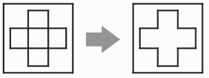
Prior to doing any sorting, the program first does a union on any touching or overlapping polygons. This is required so that the sorting routine doesn't encounter ambiguous situations produced by overlapping polygons.

Figure 4: Prior to sorting, any overlapping or touching polygons are unionized.
Step 2 - Sorting
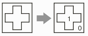
The de-embeddding routine then sorts the polygons assigning each a level - 0 for polygons not surrounded by any parent, 1 for those surrounded by one parent, 2 for those 2 levels deep and so on. This can be a very complex process when the polygons are large.

Figure 5: Polygons are sorted by their embedding level.
Step 3 - Boolean
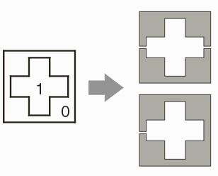
All polygons in level 1 are subtracted from those in level 0. All polygons in level 3 are subtracted from those in level 2 and so on. The output of the boolean can produces re-entrant polygons (those with a cut line) or slices (the slice option is available for some photoplot systems that have problems processing re-entrant polygons.)

Figure 6: After boolean, the resulting mask consists of only dark polygons. Two options are possible: cut-lines or sliced.
Gerber Output
Gerber output is RS247X and does not use any draws or flashes -- only the G36/G37 area fill commands.