Best Drawing Practices
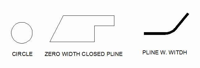
Let's start with the recommended drawing entities:
- zero width closed polylines
- polylines with width
- circles
All three of these entities share the following characteristics - they form a closed boundary with a well defined interior and exterior.

Here are entities we don't recommend using:
- lines and arcs
- hatch
Why?
Because lines and arcs don't form closed figures by themselves. While our conversion program can link the endpoints of lines and arcs to form a closed figure, this linking can be "broken" either by small gaps at the endpoints or by "extra" lines or arcs hidden under the desired ones or by "missing" lines and arcs.
You may use lines and arcs if you are very careful to always snap the endpoints to each other and not to leave any small or hidden lines under lines.
When drawing complex layouts lines and arcs are often desirable since they allow a user to trim and to generate chamfers and radii easily. In that case we recommend that you use them for that purpose on a separate layer but then "trace" over them with a polyline for the actual CAD output.
The hatch command would seem ideal for creating mask data since one can clearly see in AutoCAD what regions are "filled" and which are empty. However the hatch data that gets embedded into the DXF file is extremely complicated and most conversion tools don't support it. Therefore it must be avoided.
Avoid Self Intersecting Geometries
Even when using the zero width closed polyline (ZWCP) or polyline with width you can still go wrong by creating a self intersecting figure. In general, tools that produce masks don't support such figures or if they do their behavior is not consistent. Therefore avoid these.

< Previous 1 2 Next >
