
This page describes the basic procedure for translating a DXF file to GDSII using ASM 3500's Polygon De-Embedding feature. Activating this feature requires its own license.
Polygon De-Embedding is the ability to take a layer of polygons embedded inside of other polygons, figure out which surrounds which, and produce a GDSII output that sorts out the changes in polarity due to each boundary.
Mask shops often receive designs in AutoCAD (DXF) that assume that the mask polarity will automatically change from dark to clear with each "embedded" polygon. In fact, this does not happen, and often the mask shop or the designer has to redraw the entire database.
In the example below, all polygons (DXF closed zero width polylines) are drawn on a single layer and we can see three levels of polygons: the outer square (dark), the two irregular shaped cutouts (clear) and the three circular holes (dark.)
If converted directly to GDSII the resulting mask will be a dark rectangle since GDSII treats all polygons as filled.
This is not what we want and this is where the de-embedding option comes in. With the de-embedding option we get the mask that we expect.

Running DXF2GDS with De-EmbeddingStep 1 - Open the DXF File |
|||
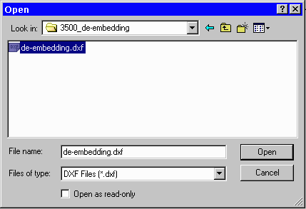 |
Start DXF2GDS and open the file you wish to convert to GDSII:de-embedding.dxf. |
||
Step 2 - Configuring the Translator |
|||
|
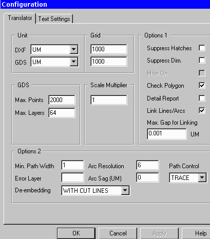
From the main menu, click on theConfiguration button to open the Configuration dialog and select the Translator tab. Set the proper units and grid which in this example is units of microns, and grid of 1000. Set the De-Embedding option to WITH CUT LINES. Click OK to save the settings. The WITH CUT LINES option instructs the de-embedding module to do a boolean operation and to generate a single large polygon with as many cut lines as needed. |
||
Step 3 - Selecting Layers to Convert |
|||
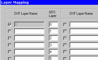 |
From the Main Menu, Click on the Layers button. The Layer Table will appear. Make sure that the layer(s) you wish to translate have been selected with a checkmark next to their layer name. In this example, the polygons were all drawn on layer "0" so that is the only layer we need to convert. Click OK to close the Layer Table. |
||
Step 4 - Starting the TranslationStart the Translation from the Main Menu by Clicking on the Translate button. Only a second should be required to complete the conversion including the de-embedding. |
Step 5 - Viewing the Results |
|||
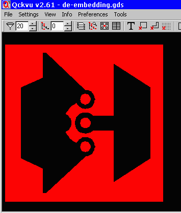 |
Click on the View GDSII button from the Main Menu to view the resulting GDSII file. Notice that in the filled view, the cutouts are visible as are the solid round pads. The polarity change that the designer intended is correctly produced. |
||
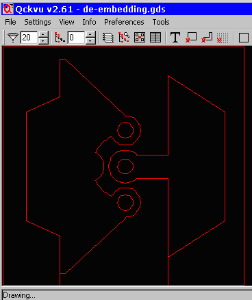 |
When viewed in outline mode one can see how the dembedding works. The outer square polygon and the two inner cutouts were booleanized to form a single "dark" polygons -- the cutout region is formed using cut lines that wrap around the empty area. The three circular polygons remain independent. |
Geometric Output OptionsThere are for choices of how the GDSII output is generated for de-embedding: Disabled - Tells the translator not to use this option. DE-EMBEDDING DISABLED Cut Lines - these are paths into and out of the polygon which are used to define re-entrant boundaries. DE-EMBEDDING CUTLINES No Cut Lines - some tools downstream cannot handle re-entrant boundaries. The No Cut Lines option slices the output polygon into as many smaller butting polygons as needed.
DE-EMBEDDING
NO_CUTLINES
Data Type - some tools downstream do not want us to merge the dark/clear polygons. So instead of creating new polygons we mark the output polygons with a datatype that indicates their level of embedding: 0=no parents, 1= 1 parent, 2= 2 parents ... The downstream tool will, of course, have to know how to interpret the data type.
DE-EMBEDDING
DATATYPE
To see an example click here .... |