De-Embedding Output Geometry Options
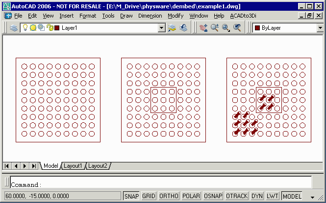
We'll show the same input file and the different outputs possible with de-embedding. You can download the test DXF file here: example1.dxf 56KB

Everything is drawn on Layer1 in DXF.
De-Embedding Output Geometry OptionsWe'll show the same input file and the different outputs possible with de-embedding. You can download the test DXF file here: example1.dxf 56KB 
Everything is drawn on Layer1 in DXF. |
||
Case 1 - No De-EmbeddingIf dembedding is disabled then no processing of the data is done and the GDSII output polygons match the DXF input polygons. Download: example1_disabled.gds 90KB 
Of course, the mask that one would get from this would be solid black. 
|
||
Case 2 - CutlinesIf cut lines are selected then the parent and children will be merged and cut lines will be used to enter/exit a polygon to define any holes in it. Notice in the image to the right, that prior to the de-embedding, any overlapping enities are first unionized.Download: example1_w_cut_lines.gds 84KB 
The mask now shows the holes as it should. 
|
||
Case 3 - No Cut LinesSome target systems can't handle polygons with cutlines. This option "slices" the dark/clear polygons so that the output is only dark polygons but none of the output polygons are re-entrant. Instead they butt up against each other. Download: example1_wo_cutlines.gds 86KB 
The mask shows the holes as it should. 
|
||
Case 4 - Data TypeFor a special requirement, our customer wanted the data de-embedded but also wanted to be able to "edit" the resulting output. This means we could not use either cut-lines or no cut-lines since the conversion makes editing impractical. We mark the embedding level using the GDSII data type on each boundary. Download: example1_using_datatype.gds 88KB In the image below, you can see that the overlapping polygons have been unionized. But you don't "see" the other effects of de-embedding since all datatypes are treated the same. 
If we color each datatype separately you can now see the differentiation. Green=0, Red=1, Blue=2 
A standard GDSII reader won't know that the data is de-embedded but if the GDSII reader has been adjusted to use the datatypes as de-embedding levels then the desired mask can be achieved and the data is still editable. |
||