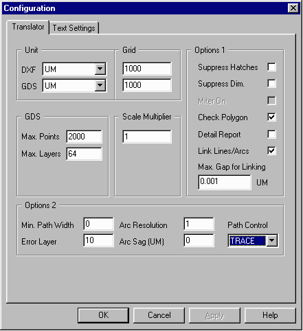
The ASM 3500 DXF2GDS Configuration Menu must be set properly otherwise data will not be translated properly and may look distorted when viewed.
|
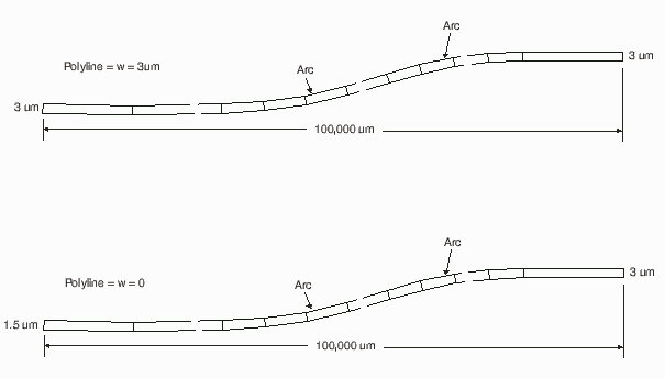
If Optical designers used IC layout tools there would be no conversion from arcs and splines to segments since no arcs or splines are allowed in such tools. In the optics world, a variety of CAD tools are used: sometimes coming from the mechanical design world (AutoCAD, Unigraphics, Solidworks) and sometimes homebrew -- especially some auto-generated layouts whose input is parameters and equations. The problem of course, is that since the mask software and tools do not support arcs, the arcs and splines must be fractured or segmented. Obviously there will be some difference between the true arc and the approximation -- but sometimes due to computational shortcuts or assumptions the introduced errors become severe. Errors in computation are often exaggerated for optical components because the radius of the arc is extremely large. |
|
The ASM 3500 DXF2GDS Configuration Menu must be set properly otherwise data will not be translated properly and may look distorted when viewed. |

|
DXF / GDS UNITS / GRIDDWG and DXF units vary (UM or MM). Click here for more information about various units and associated scale factors. The Mask shop should always be sent data in UM with .001 resolution. Since the DXF file doesn't have any unit information, the user must set the DXF units in the config file. Most vendors require the GDS output units to be in Micron (UM) and grid of 1000. When Configuring DXF to GDSII use the following scale:
ACAD UNIT        ACAD GRID        GDSII UNITS        GDSII GRID        SCALE
    MM            100,000             UM               1,000           1,000
    UM              1,000             UM               1,000              1
   MILS            10,000             UM               1,000            25.4
   INCH         1,000,000             UM               1,000          25,4000
|
MAX POINTSThe original GDSII spec limits the max number of points per polygon to 200. Most mask shops can take now polygons with up to 4000 or 8000 polygons. Consult with your vendor before defining a value. A safe value is 2000. SCALE MULTIPLIERIn case the DXF unit is Inch or MM and the GDS unit should be in UM, the user must define a scale factor. Inch to UM require a scale of 25400, while MM to UM requires a scale of 1000. ARC RESOLUTIONAutoCAD file can have circles/arcs. But a GDSII file is all vector based so the translator breaks the arcs to vectors. The user can define how fine to break the arcs. A value of 1 (degree) means the translator will replace a 90-degree arc with 90 vectors. The lower the value, the more accurate the output file and the bigger the GDSII output file would be. Range is 0.1 to 25 degree. For circular patterns we recommend using a value of .5 to 1 degree. |
MAX LAYERSDetermines the highest layer number allowed in the GDSII file. The standard value is 63. However, many CAD systems support up to 255 layers. You should leave this value at 63 unless you are sure that your target system can accept more. The maximum value you can set is 1024. LINK LINES / ARCS - MAX GAPThe link line option will link lines/arcs in the DXF file to GDSII boundaries as long as they are connected end to end OR they are within a small gap defined by the user as MAX GAP. ERROR LAYERThe GDSII file requires all polygons to be closed, were in AutoCAD a designer may leave lines unconnected by accident. When the user defines an error layer (say 20), all open lines/arcs will go to layer 20 in the output GDSII file. When the conversion is done, the user can check layer 20 with our GDSVU and make sure there is no data on that layer. |
Special Chopping Feature in DXF2GDSVersion 6.0x can handle complex boundaries drawn by the AutoCAD designer (especially circular traces for waveguides and optical designs) automatically. It breaks down these large complex boundaries into smaller ones that do not exceed the max vertex limit. EXAMPLEIn this example, there are four 0 width close plines that make a 180 degree curved polygon. The radius of the curve is 5000 microns, the width is 3 microns and the gap between the curves is about 4 microns.
With an Arc Resolution default of 9 degrees, the GDSII output will look very choppy and there is a chance that the vectors from one curve will cross on top of the adjacent curve.
This feature is only available with the DXF to GDSII software and not with other competitive products.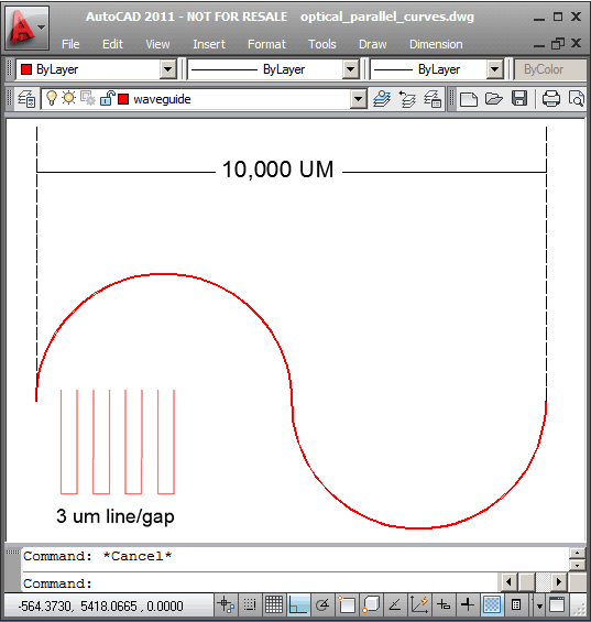 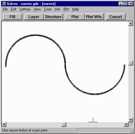 The translated file maintains the complex boundaries of the original because of the built in Chopping Feature in DXF2GDS. 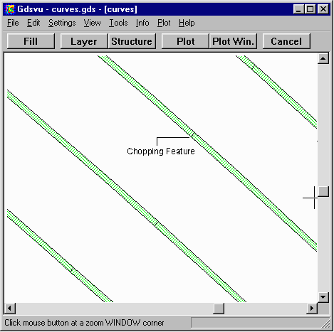 A closer view of the GDSVU file which shows how it is chopped. |