Overlap
Our client requested that, when converting the GDSII data to Gerber, any shared edges of polygons be overlapped to allow for tolerances in the data processing.
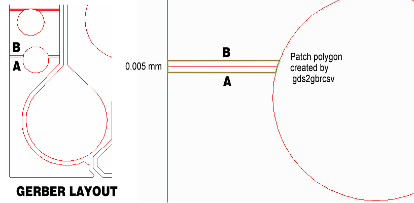
This is accomplished using the -overlap:X argument where X is the amount of overlap and is supplied in units of the Gerber file (either mm or inch).
In our example we set the overlap to 0.005 um.
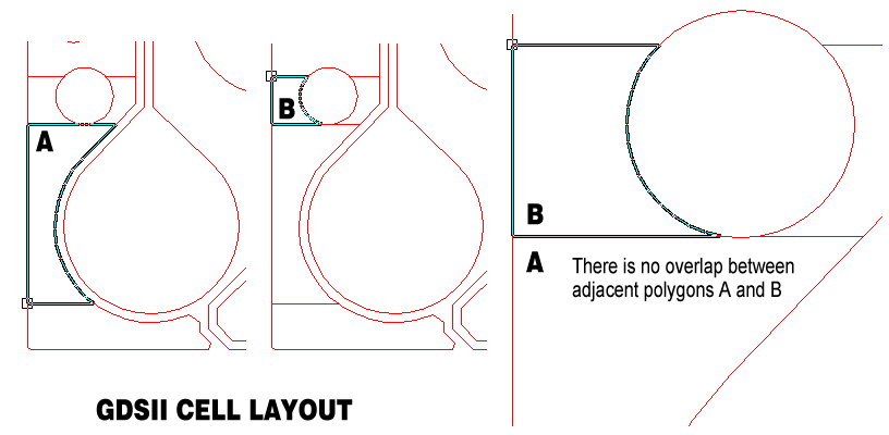
The input GDSII file consisted of a large number of "butting" polygons (as opposed to re-entrant polygons.) The GDSII file did not have any overlap - shared edges were "snapped" to grid as shown in the illustration below:

If these polygons were converted directly to Gerber, it is possible that a rasterizer which showed some pixel snapping might leave a tiny gap between the two polygons.
Solution
During the conversion to Gerber, a Boolean operator in gds2gbrcsv detects these shared edges and applies a patch of the specified width. The patch insures that any gap is covered by the rasterizer.

