web_drop_shadow.gif


Automatic Placement of Left and Right Aligment Die


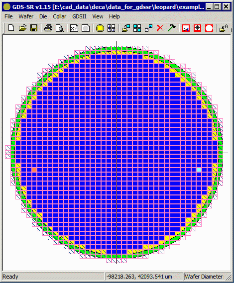
It is fairly commend when creating a redistribution mask to replace two of the product die with special alignment die - one on the left side and one on the right as shown in the snapshot at right.

In order to reduce the time needed to design the mask, we've added the ability to define the left and right alignment die in the dialog and these will be automatically placed in the array using the following rules.

  gds-sr_display.gif

Left and a right alignment die replace product die on this wafer mask.


200 mm Wafers

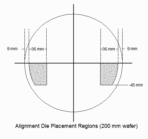
For 200 mm wafers the diagram below shows the allowed regions (hatched) where alignment die can replace product die.

alignment_die_regions_200mm.gif

The rule that the program follows is to place the alignment die as near to the X axis as possible and as near to the Y axis as possible. The actual position is dependent on the die size as the rule does not allow any part of the alignment die to fall outside of the boundary shown.


300 mm Wafers

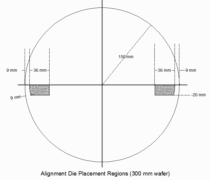
For 300 mm wafers the diagram below shows the allowed regions (hatched) where alignment die can replace product die.

alignment_die_regions_300mm.gif

The rule that the program follows is to place the alignment die as near to the X axis as possible and as near to the Y axis as possible. The actual position is dependent on the die size as the rule does not allow any part of the alignment die to fall outside of the boundary shown.


How to Define Alignment Die in the GUI

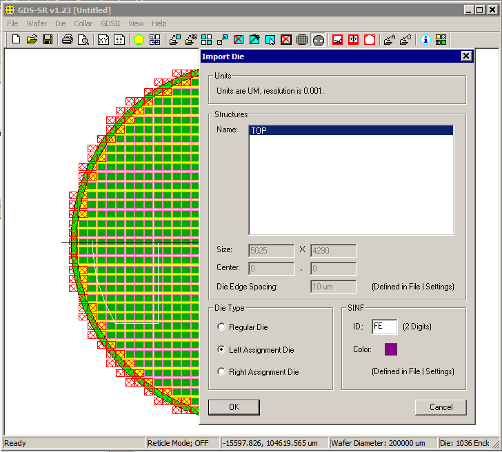
The left and right alignment die are assigned in the Die Import Dialog.

Import your product die first; either a single die or use the reticle option. Once that is complete (because unless you already have your product die arrayed, you can't replace a product die with an alignment die) then import one of the alignment die from the Die | Import Die ... dialog.

import_die_drop_down_for_alignment_die.gif

After selecting the die, you will see the Import Die Dialog. Mark the die as either a Left Alignment Die or a Right Alignment die and modify the SINF ID so it will be recognized not as a product or good die but as a special die using a code such as FE or FF.

align_die_auto_dialog.png

Then click on OK.

Repeat this process for the alignment die on the opposite side.


Scripting

Autoplacement of left and right alignment die can also be achieved when driving GDS-SR from a "script" file.

Assuming DIE-1 is your product device, then your "script" would have two additional entries (DIE-2 and DIE-3) for the alignment die:

[DIE-2]
INDEX=2
FILE=E:\cad_data\sample\left_align_die.gds
STRUCTURE=TOP
SINF=FE
RATIO=0
ALIGNMENT=LEFT

[DIE-3]
INDEX=3
FILE=E:\cad_data\sample\right_align_die.gds
STRUCTURE=TOP
SINF=FF
RATIO=0
ALIGNMENT=RIGHT

The important keyword is ALIGNMENT. When the program sees this followed by RIGHT or LEFT it will automatically replace the product die with a left or right alignment die. If ALIGNMENT is missing then no automatic placement is done (but you can still use CHANGE_DIE in your script to do the replacement)


Program Operation Video Tutorials Download Revision History Price