
|
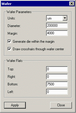
Wafer DefinitionThe first step in using GDS-SR is to define the wafer's dimensions and margin. |

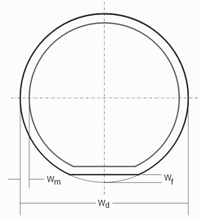
The wafer is defined by: Units - while different units are supported, it is mandatory that the wafer units match the GDSII die units - for all practical purposes this is um. wafer diameter (Wd) - typical diameters range from 100,000 um (4 inch) to 300,000 um (12 inch). |
 margin from the edge of the wafer (Wm) - no part of an arrayed die may extend into the margin area. Typically this margin is about 5000 um. wafer flat size (Wf) - the wafer has a “flat” cut into the bottom for orientation purposes. This may further limit the placement of die in that region. Newer wafers use a notch that normally does not penetrate past the margin. |
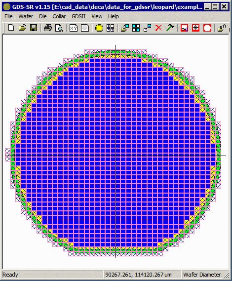
Enclosed Die vs. Margin DieDie which are completely inside of the margin (no part touching or crossing the margin) are called enclosed die. If the user wants to generate die that touch and cross the margin then the box Generate Die within the Margin should be checked. This will generate die along the periphery of the wafer but they will be marked as not valid in the internal database. Why would you want to create such die? Generally because you will use a clipping routine to cut them to the margin edge. The "sacrificial" parts of the clipped die act as a buffer between the transition from good die to the edge and result in better etching and plating uniformity. |
 Solid blue die are completely enclosed. Die with crosshatch fill are margin and used for sacrifical clipping. |
| Program Operation: 1 2 3 4 5 6 7 8 |
| GDS-SR Home | Download | Revision History | Price |