
 |
GDS-SR Reticle Input |
|
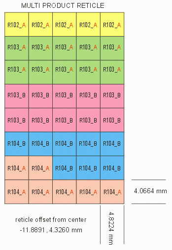
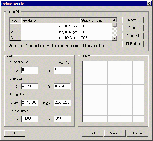
Designers of wafer level masks (chip scale packaging) need to align their structures with the devices on the existing wafer. The foundry that created the wafer often provides the positioning data not for individual die but for the reticle used by the stepper. GDS-SR can import reticle parameters and use that information to step out die over the wafer. It easily handles mixed product wafers (MPW) and is able to determine which die fall inside the wafer and which fall in the exclusion area or completely outside the wafer. At right you can see a 5x8 reticle with 5 different die variations on it. The foundry provides the die step values inside the reticle, the reticle step size and any litho offset that should be applied. |
|
|
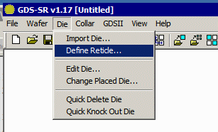
If you are given such data (and the associated GDSII files for each product) one can use the Define Reticle dialog to quickly generate the correct array. |
|
|
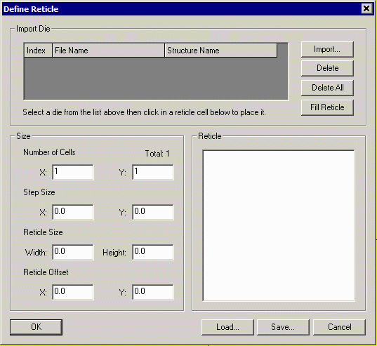
A dialog for defining the reticle will appear. The first step is to load the GDSII files for the various products that belong to this reticle. Use the Import ... button to open a dialog enabling selection of one or more GDSII files - each will be a die that is a member of the reticle. |
|
|
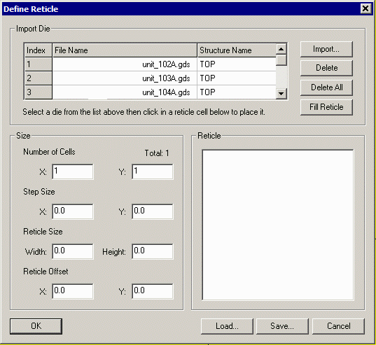
Once the various files have been loaded it is time to enter the number of cells in the reticle along with the die step size (or if you have the reticle step size you can enter that and the die step size will be computed.) |
|
|
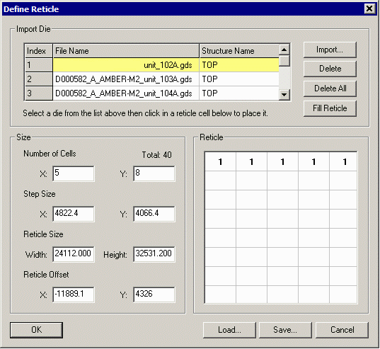
You will now see that there are some empty fields for assigning the correct product to a position within the reticle. In order to place die into position, first highlight in the upper window the die you want to place by clicking on it. Then click in the appropriate boxes where this die should appear. |
|
|
The first die imported (index = 1) has been highlighted; the user clicked on the four positions across the top row of the reticle. The user selects the second die, clicks on the positions, the third die and so on until the entire array is filled. 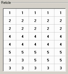
|
|
|
All of the reticle build up information can be saved as a text file by using the Save ... button and recalled by using the Load ... button. Generating the Array To create the array click on OK. Your wafer will be filled by stepping the reticle - then the die placments are computed and any die that fall outside the wafer are deleted. 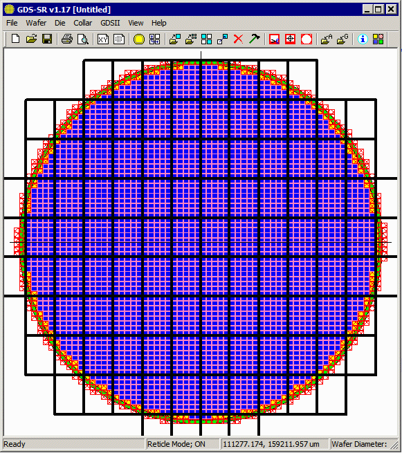
The program reports how many die are completely enclosed within the margin and how many sacrificial die have been placed region between the outer edge of the wafer and the margin. (Only of course, if you have specified to generate the sacrificial die when defining the wafer diameter and margin.) |
| Program Operation: 1 2 3 4 5 6 7 8 |
| GDS-SR Home | Download | Revision History | Price |