 |
Knocking Out, Replacing and Deleting DieKnocking out some of the arrayed die (circuits) is often necessary to expose underlying features on the wafer. There are two ways to do this: if the die are large enough you may prefer to click on one from the display to knock it out. If the die are small or if you want to drive the process from a file you can use a window or coordinate to specify which die to knock out. Change Placed Die To change or knockout die from the dialog use select the Change Placed Die menu item from the Die drop down: 
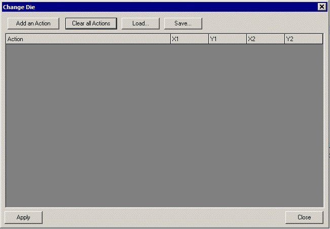
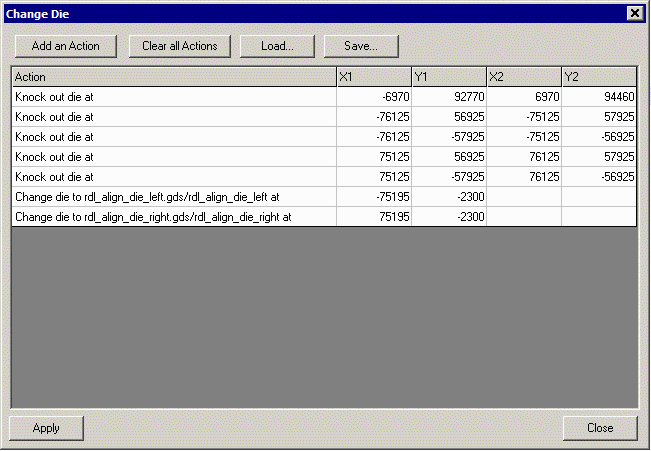
The following dialog will open:  The user adds "Actions" and specifies either a single coordinate or a window (LL,UR) to which an action applies. Available Actions are: Change Die - Used to change an already arrayed die to the one listed in the action Knockout Die - used to mark a die as knocked out. This does not delete it from the database but marks it as "bad" for the SINF output. It remains in the GDSII output. Delete Die - removes a die (or number of die) from the database Remove this action - removes the action (assuming you defined an action and don't want it any more.) Example of Various Actions  The first 5 actions are all "knockouts" intended to mark various placed die as invalid. We selected knockout instead of delete because we are actually going to use the Hextract clipping program to remove these regions. If we wanted to remove the entire die we could have selected the Action "Delete." The last two actions are die replacements. We previously loaded 3 die - the unit die (which was arrayed to cover the entire wafer) and two alignment die - one for the left side and one for the right side of the wafer. We now wish to replace a unit die with an alignment die at a specified coordinate. Notice that the actions for replacing a die use only a single coordinate. The program will find whatever die covers this coordinate and replace it. The user does not need to specify the exact center -- any point inside the die's extents will work. Saving and Loading Actions If you find yourself creating masks for a series of wafers that are identical in layout (i.e. the knockouts are in the same locations, the alignment die are the same and so on) then you can save these actions to a text file and load them later for use again. Use the Save and Load buttons. Here is an example of the text file for the actions shown above: -6970 92770 6970 94460 KNOCKOUT -76125 56925 -75125 57925 KNOCKOUT -76125 -57925 -75125 -56925 KNOCKOUT 75125 56925 76125 57925 KNOCKOUT 75125 -57925 76125 -56925 KNOCKOUT -75195 -2300 -75195 -2300 rdl_align_die_left.gds/rdl_align_die_left 75195 -2300 75195 -2300 rdl_align_die_right.gds/rdl_align_die_right Notice that even though we entered only one coordinate for the replacement die, the program repeated that coordinate for both positions of the window. If you are creating these files from a text editor do the same. |
| Program Operation: 1 2 3 4 5 6 7 8 |
| GDS-SR Home Page | Download | Revision History | Price |